Nike M5 (and M5E1, M88) Scale Data

Navigation and Links

NikeM5E1 Those who enjoy modeling sounding rockets are probably familiar with the name “Nike”.  The Nike M5 and M5E1 motors were originally developed for use in the boosters of the Nike-Ajax and Nike-Hercules missile systems, but they also found a place as major component in sounding rocket vehicles of various configurations.  For more information on the history of the Nike missile systems, visit such sites as the Nike Historical Society, Ed Thelen’s Nike Missile Page, and others.

Nike Motor Versions (M5, M5E1, M88)

hercules_holes The M5, M5E1, and M88 are the three versions of Nike motor that were manufactured.  According to Ed Thelen’s Nike Missile Page the M5 motor of the Nike-Ajax system was modified for use with the Nike-Hercules system (cluster of four M5E1 motors) by drilling and tapping extra holes in the motor body.  This was the only difference between the M5 and M5E1 units.  According to Stephen Maire, the M88 motor replaced the M5E1 in the Nike-Hercules system later in its operational life–the change in designation is probably related to the uprating of the motor’s performance and probably does not refer to any major external changes.

Nike Motor Drawings and Documents

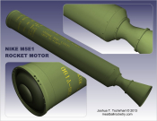
nike_m5 nike_m52 These drawings by Bob Biedron* give some basic information on the motor itself without shroud or fins.  One caveat: the Nike’s nozzle is conical and does not actually have that gradually curved shape as seen in the drawings.  There is a slight discrepancy between the sketch and the line drawing regarding the location of the aft circumferential weld.  The sketch predates the line drawing by several years and is verified as more accurate by comparing with other data such as nozzle shroud and screw hole positions (relevant dimension corrected on the line drawing by Josh with footnote 6/26/12.  Click here for the original unedited version).

Sounding Rockets & Specified Nike Motor Designations

Official documents regarding particular sounding rocket prototypes will sometimes show a specific Nike motor designation in a drawing.  Given the superficial differences between the M5 and M5E1, I do not generally think that these references denote a hard-and-fast requirement for one motor type over the other.  Thus in reality one will find different rounds of similar vehicles using either type (for example, one illustration for the Nike-Tomahawk’s interstage adapter lists M5, M5E1, and M88 as all being compatible).

nikefins Variations in Fin & Nozzle Shroud Design

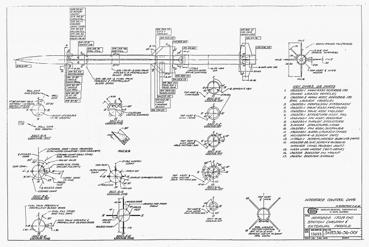
Click on the right-hand preview image for a 12-page Atlantic Research Corp. brochure (in PDF format) about different Nike Fin designs as used in various sounding rockets.  The original document came from Bob Biedron’s collection.

Variations in Forward Flange

The flange at the forward end of the motor seems to vary somewhat between vehicles.  Note the two variations in the Biedron drawing above.  I have noticed other variations during my own visits to examine actual motors on display, such as a longer lip at the top of the flange (ranging between 1.18″ long to as long as 1.38″, as opposed to the .925″ length on the Biedron drawing–I have not yet seen in person a Nike with the lip as short as .925″).

According to John Hugh Boyd in a Scaleroc Yahoo Group message dated 6-26-04, the Nike motors used a 16″ nominal 800# ANSI standard pipe flange (a.k.a. 16 inch heavy-weight) used in pipelines and refineries (John worked for a pipeline engineering consulting firm).  He suggests that the reason for the difference in flange shapes (flat conical vs. rounded ‘scoop’ scape) is due to a differences in flange manufacturer (of which there are several), and he suggests there are quite possibly even more versions in existence.

More Variations from Nominal Design

Other than the slight variations shown in the above documents, there are other notable changes between vehicles.  I have usually seen the longitudinal weld in different positions than is shown in the Biedron drawing.  I do not know if this is due to a subsequent change in motor design or if perhaps the variation was considered within tolerance all along.

nike-tomahawk_launcher Modifications for Sounding Rocket Flights

Depending on the type of launcher used (such as the one shown at right), extra holes may be drilled and tapped in the Nike’s forward flange and aft area (forward part of the nozzle shroud) in order to mount appropriate launch lugs.  Sounding rockets that use the Nike-Ajax launcher would not require modification.  The Nike Tomahawk round shown in the linked launch photo used T-shaped lugs mounted on the side of the motor opposite the standard Ajax lug position (the same forward lug design is also used on one of the Argo D-4 Javelin’s Nike stages).  Rockets launching from towers typically use multiple sets of 3 or 4 launch lugs radially spaced around the airframe and may require extra holes at the forward part of the nozzle shroud (rather than the forward flange).

See below for lug drawings and one example of extra holes drilled (though not used) in the Nike’s forward flange. [Note: Aerobee 350 photo example removed 2020-05-14, as drawings obtained in 2016 show that the holes in that photo are in fact standard holes; the motor in the Aerobee 350 system is simply rotated differently than might be considered ‘typical.’]

GC7-236-FWD-LUG-NASA GC7-237-AFT-LUG-NASA odd_flange_holes

“Unpainted” Motors and Stenciled Lettering

Unpainted motors (i.e. olive drab with yellow stenciled lettering) have sometimes been used in sounding rocket flights.  Here are some photos of a Nike-Orion clearly showing the style of the stenciled lettering on an M5E1 motor with factory paint scheme.

External Links/References

Nike Historical Society
Ed Thelen’s Nike Missile Web Page
Nike Hercules page at Rocketry Online (including information by Stephen Maire)


*NOTE:  All drawings by Bob Biedron are posted with his permission.

Saturn I Data

Saturn I Drawings

SMR Dimensioned drawings of the Saturn I (Block 1 and Block 2 vehicles) and the Saturn IB are provided in Peter Alway’s Rockets of the World, Fourth Edition , which is available through NARTS.  The drawings in Rockets of the World are not nearly as detailed as those in Peter’s first book, Scale Model Rocketry: A Guide for the Historian-Craftsman (1990), now long out-of-print.  As of December 2008, Peter is graciously allowing me to post his Saturn I Block 2 drawings on our Meatball Rocketry site, at least until the drawings can be published again for sale.  So for those who have been longing for something more substantial, your wait is over.  Click on the page thumbnail below for a PDF file containing the Alway drawings.

SMR130 Note that there is no color scheme page printed ( Scale Model Rocketry p 131); the scheme contains several errors that were subsequently fixed in Rockets of the World.  I suggest you refer to that source, as well as NASA photos, for color pattern and markings.  Other numbered pages that appear to be missing contain no drawings, only photos.

Saturn I Data Discrepancies

There are a few data conflicts between the drawings by Peter Alway and some other data sources.  I will post brief discussions of these discrepancies as time allows.


Saturn I Photo Links

NASA images of varying quality can be found at www.apolloarchive.com.  Look under the image gallery section titled Early Apollo.

Look for some interesting illustrations and photos such as this in the Saturn Illustrated Chronology.

Medium quality detail photos of the Saturn I at the U.S. Space & Rocket Center in Huntsville, AL are available by clicking here (scanned photos by Josh)

Much better photographs of the Huntsville Saturn I and other rockets can be found at HistoricSpacecraft.com.

sa52 sa53 sa51

Saturn Construction Tips 3

How to Draw a Mitered Tank Template

PART 1 – Logistics of the Clustered Tanks
PART 2 – How to Draw the Tank Fairing
PART 3 – How to Draw a Mitered Tank Template

For the 1:59 scale Saturn, I used an unusual method of “mitering” the ends of the tank tubes to fit over a conical shroud rather than fitting within the shroud.  The following page will show how one can develop a template for cutting this part from a tube or to make a cardstock part that can be rolled into a tube.  Click on any small drawing for a larger version.  Feel free to print the larger drawings as a visual aid.

Before you can begin…

You need at least three pieces of information before you can begin:

  • Tail section outside diameter
  • Tank tube outside diameter
  • Tank spacing (typically the outer diameter of the tank cluster)

These dimensions will vary due to scale and the parts used.  If part sizes are “fudged” in any way, some time may need to be spent arranging the parts in CAD to optimize the layout, minimizing variation from true scale as much as possible.  When the layout is finally settled, you can  move on to step 1.

Steps 1 through 4 are the same drawing process used in Part 2, although the text descriptions may be slightly different.

NOTE:  Many of the following drawings have been simplified for clarity.  Superfluous overlapping lines and arcs have been cut to make the drawings appear cleaner than the original.  Also, note the line color changes from each step to the next.  Typically (but not always), red denotes current drawing activity and gray shows items that were previously drawn .  Some lines (new and old) remain black for clarity.

shrouddwg1 Step 1

Begin by drawing the top view as shown using known dimensions.  Add an additional circle that intersects the center points of the tank tubes (this will serve as the top of the cone that the tanks sit on).

The side view is developed using the top view and is aligned directly beneath the top view.  The triangle’s sides are 60° relative to the base.

Note:  If your model’s design requires a different cone top diameter or height (as the 1:59 scale model did), you will need to modify the drawing of your cone accordingly.


shrouddwg2 Step 2

Separate the righthand tank tube into 16 slices.  One way to accomplish this is to draw a single line of a different color, then use the Radial-Copy tool.


shrouddwg3 Step 3

Using the center points of the large circles, draw concentric circles or arcs (I use the Circle Center and Point tool) through the intersection of the lines (from Step 2) and the tank tube, making sure that the arcs intersect the horizontal tank centerline.  Notice that not all segments are used to draw the arcs; only one arc left of the inner circle is drawn.

Note:  If your cone top is of a smaller relative diameter, you may need to draw additional arcs through the remaining line segments from Step 3.  I do this by default, simply to give myself plenty of “wiggle-room” for potential changes in design.  The important thing, however, is to make sure you have at least one arc drawn to the LEFT of the cone top circle.


shrouddwg4 Step 4

Draw vertical lines (I typically use the Parallel Line tool) through the intersection of the arcs (in Step 3) and the horizontal tank centerline, down to intersect the right side of the triangle.  Also draw a line down  from the right-most edge of the tank.


tankdwg5 Step 5

To the right of the cone side view, create the body of the tank template in line with the side view, using two vertical lines spaced apart the value of the tank tube’s circumference (pi x d or 3.14159 x diameter).

Be sure to also transfer the horizontal lines to the new template.


tankdwg6 Step 6

Divide the template into 16 sections (in the X-direction). <—->

I use the Linear Fit Copy tool to accomplish this (fitting 17 lines in the given space creates 16 sections, as the first and last line coincide when the template is wrapped around the tube).

I typically make the center vertical line a different color to make it stand out.


tankdwg7 Step 7

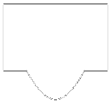
Draw horizontal lines from the intersection of the vertical lines drawn in Step 4 and the right side of the triangle.


tankdwg8 Step 8

Use the Bezier tool (Spine by Fit Points should also work) to make a curve at the intersection of the horizontal and vertical lines as shown (ignore the black horizontal lines for this step).

Note and Tip:  If  you have a different cone top diameter and thus have additional horizontal lines to contend with, you will need to use a different start point.  In this case, it may be easier to add an extra step… Before using the Bezier tool, first draw a polyline starting at the lowest intersection (in the middle) and work backwards through each intersection to find your start point.  Then use the Bezier (or Spline by fit points) tool, working from left to right as needed.

Do NOT start the Bezier tool at the bottom of the curve to draw the curve in two halves; the resulting shape will be slightly distorted at the base.


tankdwg9 Step 9

Clean up the template by deleting unnecessary or overlapping lines.  I prefer to preserve the vertical lines as a sight reference when working on the model.  The template is accurate, but will possibily need modification for real-world use.  See suggestions for modification below.


tankdwg_total Visual Summary

Here is a drawn summary that may help you to visualize the development process:


Modifying the Template for use as a wrap-around cutting guide

x = pi(t + 2p)

x = needed template width

t = tank tube diameter

p = paper thickness (I find inkjet printer paper to be about .004″)

If you intend to use a paper wrap as a cutting guide, it needs to be made wider to fit around the tube.  Take the actual tank tube diameter and add the thickness of two layers of paper to it.  Multiply their sum by pi (3.14159).  The resulting value is the needed X-dimension of the cutting guide wrap (sideways).  Expand the template in the X direction only.

The resulting paper template may be slightly too large, so adjust the template width accordingly and reprint.  The same thing can be done to make a cutting guide out of cardstock, fiberglass, or any other material, bearing in mind to only change the X-dimension of the template only.


crdstktank3 Modifying the Template for rolling into a 2-layer cardstock tube

For the 1:59 scale Saturn model, I constructed the lowest portion of each tank tube from two layers of cardstock (the inside layer offset slightly upward to give the tank a nice sharp edge). The two layers would first be glued together flat, then curled and joined. The completed cardstock section would then be coupled to the main paper tube.

Due to the expansion/compression properties of two layers of cardstock that are glued before rolling, the template will need to be reduced in the X direction.  I found that taking the average of the intended diameters of the tank [(O.D. + I.D.)/2] was an effective solution.  The new circumference was then determined (pi x diameter), and the width of the template was modified accordingly and printed directly onto cardstock.

TankLayout_07 With some extra planning, a glue tab can be built into the design of the inner layer by offsetting the left and right edges of the bottom (inside) layer — see right.

Saturn Construction Tips 2

How to Draw the Tank Fairing

PART 1 – Logistics of the Clustered Tanks
PART 2 – How to Draw the Tank Fairing
PART 3 – How to Draw a Mitered Tank Template

As previously stated in Part 1, the traditional method for transitioning from the cluster of 8 tank tubes to the lower tail section is to use a conical shroud with “scalloped” cut-outs that fit around the tanks.  Since many modelers will need to compromise true-scaleness of tube sizes for various reasons, most models will require drawing this fairing from scratch.  The following page will show how one might go about “developing” this part in a CAD or other drawing program (it also works using paper and pencil with the correct drawing tools).

UPDATE:  If you don’t want to draw your own, you can use Steve Humphrey’s Transition Maker.

Click on any small drawing for a larger version.  Feel free to print the larger drawings as a visual aid.

Before you can begin…

You need at least three pieces of information before you can begin:

  • Tail section outside diameter
  • Tank tube outside diameter
  • Tank spacing (typically the outer diameter of the tank cluster)

These dimensions will vary due to scale and the parts used.  If part sizes are “fudged” in any way, some time may need to be spent arranging the parts in CAD to optimize the layout, minimizing variation from true scale as much as possible.  When the layout is finally settled, you can  move on to step 1.

NOTE:  Many of the following drawings have been simplified for clarity.  Superfluous overlapping lines and arcs have been cut to make the drawings appear cleaner than the original.  Also, note the line color changes from each step to the next.  Typically (but not always), red denotes current drawing activity and gray shows items that were previously drawn .  Some lines (new and old) remain black for clarity.

shrouddwg1 Step 1

Begin by drawing the top view as shown using known dimensions.  Add an additional circle that intersects the center points of the tank tubes (this will serve as the highest point of the fairing).

The side view is developed using the top view and is aligned directly beneath the top view.  The triangle’s sides are 60° relative to the base.


shrouddwg2 Step 2

Separate the righthand tank tube into 16 slices.  One way to accomplish this is to draw a single line of a different color, then use the Radial-Copy tool.


shrouddwg3 Step 3

Using the center points of the large circles, draw concentric circles or arcs (I use the Circle Center and Point tool) through the intersection of the lines (from Step 2) and the tank tube, making sure that the arcs intersect the horizontal tank centerline.  Notice that not all segments are used to draw the arcs; only one arc left of the inner circle is drawn (though I sometimes draw two).


shrouddwg4 Step 4

Draw vertical lines (I typically use the Parallel Line tool) through the intersection of the arcs (in Step 3) and the horizontal tank centerline, down to intersect the right side of the triangle.  Also draw a line down  from the right-most edge of the tank.


shrouddwg5 Step 5

Copy the triangle and vertical lines (from Step 4) to an unused part of the workspace.  Using the top vertex of the triangle as a center point, draw concentric circles or arcs through the intersections created in Step 4.

Draw circles or arcs (of a different color) through the lower right corner of the triangle and the right endpoint of the line above it.

Draw a horizontal line through the top vertex of the triangle, extending to the outer edges of the the arcs or circles.  You may want to “trim” any overlapping arcs below the new line (or copy the drawing and trim it elsewhere, just-in-case).  This will form the body of the final fairing template.


shrouddwg6 Step 6

Return to the Top View and draw line segments from the center of the large circles to the end points of the line segments from Step 2.


shrouddwg7 Step 7

Measure the angles of the lines created in Step 6 (relative to horizontal) and record them in order (I usually measure the angles’ precision to 3 or 4 decimal places).


shrouddwg8 Step 8

Starting from the center point of the arcs created in Step 5, draw a line 11.25° to the outermost circle.  This will be the center line of the tank cutout.


shrouddwg9 Step 9

Take the angle measurements that were recorded in Step 7 and divide their values in half.  Use the Radial-Copy tool to copy the tank center line five separate times, using the new angle values to space the new lines.

The lines could also be drawn individually with the Line tool by adding 11.25 to the halved angle values.


shrouddwg10 Step 10

Using the tank center line as an axis, Mirror-Copy the five lines created in Step 9.


shrouddwg11 Step 11

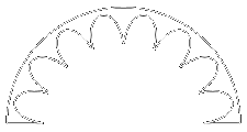
Use the Bezier tool (Spline by Fit Points should work also) to connect the intersections of the lines as shown.  Only the innermost black (left) and outermost black (right) arcs are ignored in this step.


shrouddwg12 Step 12

Use the Radial-Copy tool to make a total of 8 curves around center point, spacing them at 22.5°.


shrouddwg13 Step 13

Delete all concentric arcs except the outermost and innermost black arcs.  Then trim everything that overlaps the inner black arc.  The shroud is now complete.


shrouddwg_total Visual Summary

The following is a drawn summary that may help you to visualize the development process:


Continue to Part 3. . . How to Draw a Mitered Tank Template

Saturn I & IB Construction Tips

Part 1 -- Logistics of the Clustered Tanks

PART 1 – Logistics of the Clustered Tanks
PART 2 – How to Draw the Tank Fairing
PART 3 – How to Draw a Mitered Tank Template

Building a Saturn I or IB model from scratch can be a tedious undertaking. Proper planning is imperative for satisfying results, but it can also be the most time-consuming part of the modeling process. In designing and building my own models, I have found a CAD program to be an indispensible tool for working with complex components such as the Saturn’s cluster of 8 fuel tanks in the S-I first stage, as well as the scalloped fairing at the rocket’s base.  These parts are among the most daunting for a scratch-builder and demand special consideration early on in the design phase.


Scale S-I Tanks vs. Oversized Tanks

2saturns08 star As far as I can tell, most Saturn IB kits so far have employed slightly oversized tubing to represent the S-I booster fuel tanks, allowing the modeler to glue the tubes to a round “core” with no space between the tanks. The real Saturns, however, had slight gaps between the tanks. Tank tubes (both scale and oversized) can be spaced accurately using two or three star-shaped centering rings that fit over an undersized core (stuffer) tube (Figure 1). It can be difficult to accurately cut rings as such, so I recommend using resin-casting technology to make exact copies once a suitable “master” pattern has been made. Laser cutting is another viable method for making consistent rings.

Although the difference between “scale” and oversized tanks is not very noticeable even on large models, the benefit of using the small tubes is the elimination of issues that might throw off tube alignment. Depending on the availability of proper size tubing (or the modeler’s ability to make tubing from scratch), the modeler may be forced to use oversized tubing and therefore must pay careful attention to the fit before gluing.*

*NOTE: Smaller Saturn models (under 1:100 scale) will be more sensitive to paint buildup, so keep this in mind when planning your tank layout. I had some difficulty with this on my 1:165 model; the overscale tanks ended up being slightly oval-shaped after gluing them in place around the core.


S-I “Scalloped” Tank Fairing

shroud tank_attach There are two methods for simulating the scalloped shroud at the base of the Saturn booster. The most widely employed method is to use a cardstock shroud with the proper elliptical cutouts to fit over the tank tubes (Figure 2). This is the method used on my 1:165 scale model. Some kits have used injection-molded plastic parts (including the current Apogee Components kit), but for scratch-builders it can be a nightmare to make a usable shroud unless one has some idea of where to begin.  See Part 2 of this series for tips on drawing this part, or you can use Steve Humphrey’s Transition Maker to draw the part for you.

The second method is to use a standard tapered shroud and to cut out a “notch” at one end of each tank tube so that it sits on top of the shroud (Figure 3). I first heard of this method from international scale modeler Jay Marsh. I used a variation of this technique on the 1:59 scale Saturn I.  “Mitering” the bottom of the tubes eliminates the difficulty of lining up a flimsy scalloped shroud over a wide base and allows for easier application of details to the tanks prior to painting and installation. It also accommodates more variation in design of the motor mount since the tank tubes do not extend into the model’s base. Jay Marsh recommends making a cutting guide using a fiberglass “master” pattern that slips over each tank tube, but a paper or cardstock wrap may be sufficient (Figure 4). It is imperative that the conical shroud be consistently shaped and aligned properly during installation so that the notched tube ends require little modification (aside from minor sanding) to fit properly.  See Part 3 of this series for developing a template for cutting notches in the tanks.

tank_cut NOTE: Tube cutting must be a precise operation so that all tanks will sit evenly at the bottom and the top–this is more critical for the Saturn I, as both tube ends will be visible (most Saturn IB models have tanks that extend up into the interstage body so that the tops are not visible).  Mark each tank and its intended mounting location with corresponding numbers to help keep things in order.  Cutting and adjusting the bottoms of all the tanks should be done before the much easier step of trimming the tops–in case any mistakes are made.  A rigid, flat centering ring may be used as a visual guide during the cutting and sanding of the tops (I used the Interstage assembly as a guide during my 1:59 model project).


Continue to Part 2. . . How to Draw the Tank Fairing

Astron Farside

1981

farside My first rocket memories are of my dad showing my brother and me an unpainted 3-stage Estes Astron Farside when I was four.  My dad was big on simple paint schemes.  I recall orange overall (as in Testors competition orange) and perhaps a white nose cone, though maybe black was applied as well.  Shortly thereafter the rocket was painted and then flown from a local school, losing one of the lower stages.  The remaining stages were given to me, but that model was not flown again.  I credit that experience (thanks, Dad!) plus the first Space Shuttle launch as the primary inspirations for a life-long love of model rocketry.

c. 1986-87

farside_2 tr-2_crop The Farside remained a favorite kit, and to my great surprise was discovered again at a local hobby shop which had all sorts of kits with older style cards (see example above) while I was still in elementary school.  I attempted to recreate the color scheme of my first rocket but with embellishments (I took my cues on detailing from the illustrations in the Estes Tech Report TR-2 on multi-staging that came with the kit–see Ninfinger.org link and cropped image to the right).  The first (or second) flight resulted in a lost upper stage, despite using the smallest available motors, leading me to rebuild the upper stage.  That was the first time I ever ordered from Estes’ parts catalog and the first time I ever had to cut a body tube.

2002

jessfarside Jess built her Farside in 2002 using the instructions from my old Farside kit, but substituting the balsa fins with 1/16″ basswood for ease of finishing using spray primer alone.  For her version, she eliminated the payload section entirely and lengthened the model using a stock 18″ BT-50 for the upper stage.  She also added a launch lug to the upper stage (normally only a long single lug on the second stage) to allow for single stage flying.  She gave the model a nice smooth finish by applying Testors Acryl paint with an airbrush.  So far, Jess has flown it several times with complete success, using a streamer for the third stage instead of a parachute (I highly recommend using a streamer to better ensure recovery of this high-flying design).

One of these days I may build another one, too.


Kit Instructions

Astron Farside & Farside-X (larger payload version) kit instructions are available at Jim Z’s website.  Note on upper stage body tube length:  According to a Body Tube Reference guide assembled by John Brohm, the BT-50H (upper stage body) is actually 7.75″ long, but the instruction sheet shows an incorrect length:

The kit instructions list the BT-50H as 7-1/2” long; this is clearly an error as this information is not consistent with the Parts Catalog listing or the actual measurement taken of the kit part.


Related Links

Blorange 1 & 2

blorange The name Blorange, if you couldn’t figure it out, is a combination of blue and orange.  The original Blorange (smaller model), is actually the BT-50-based Redliner kit by Custom Rocket Company and was Jess’ third rocket kit.  With a unique fluorescent orange and metallic blue paint job in lieu of the standard red-and-white scheme, a name change seemed appropriate.  The larger model on the left is Blorange 2, a BT-60 upscale of the original and Jess’s first D-powered model.  It also flies well on 24mm C11-3’s.

One other change from the stock design for both sizes was the incorporation of canted fins for continuous spin during flight.

redliner A note on nose cone selection for Blorange 2:  Estes PNC-60A would be a more “scale” choice, though Jess has used both the longer Der Red Max-style cone (PNC-60AH), as well as the Custom Rocket Company PC-60, both of which look great.

Due to crimping above the fins over several flights, both models have been rebuilt at least once.  As of 2014, Blorange 1A is still going strong, but Blorange 2B was lost at ECRM-38 in 2011 the same day as the Iris.  It is currently waiting to be rebuilt.

SA-5 Saturn I (1:59) Page 6

Future Design Modifications

During the construction of the 2008 model, I struggled with the desire to make improvements to the model’s design that would be too time consuming.  But now that the model has flown, I can plan those changes that may show up in future models. . .

Spherical Recesses in the Instrument Unit

At NARAM-50 Peter Alway and I discussed several of the details that we did not do on our respective SA-5 models (Peter’s model is in 1:69 scale).  On both our models, the four spherical recesses of the Saturn I’s Instrument Unit were approximated without their distinctive spherical shape.

Shortly after NARAM I began brainstorming some ways I could simulate this detail.  I decided on a one piece casting that will fit through a hole in the body tube wall. After my third attempt to create the master pattern, I took some photos of the part (see photos to the right).  For a comparison with the real thing, go here (external link).

The part will need to be primed and sanded smooth before pouring the rubber for the mold.  The final casting will be much shallower than the pattern, perhaps no more than 1/4″ total height.

The basics of the master pattern:

IU_detail The body is a two-layer wrap of cardstock (close in size to a BT-20). The internal tube is for reinforcement only.  The spherical disk is .02″ styrene heat-formed over a 1.75″ wood doll head, then cut to the proper diameter with a circle cutter, using the back of the blade to score the cut.  The spherical disk is inserted snugly into a hole in a flat scrap of .02″ styrene, then CA’d from the back.  The disk/scrap combo was then glued on top of an additional .02″ styrene layer for reinforcement (with a small hole cut in the middle for glue access), then cut down to the final diameter for proper fit within the cardstock tube.  The internal brown tube is for reinforcment, but with a nice square cut at the end it also aided in positioning the styrene unit before final gluing.

The plan is to have an hole cut-out in a 2.6″ dia plywood or fiberglass tube (same size as BT-80). The outer lip of the detail should sit flush with the outer layer of tube and will need some sort of filler at the joint. The plastic strips on the master pattern form ‘stops’ that will help position the part (and since they’re narrow, they should be easy to adjust on the final castings). Four of the longitudinal lines are scored and will show “valleys” in the casting that help orient the part visually before gluing.

For a more typical 1:70 scale model, a 1.5″ dia wood sphere or doll head would work.  Bear in mind that I’m using diameters larger than Peter’s drawing shows due to some Instrument Unit data and a (low-res) photo I have come across.  If anyone wants more information on this, feel free to send an email.  I may eventually post that here.

I will add further information as things progress and as time allows…


Acknowledgments

SA-5 Saturn I (1:59) Page 5

NARAM-50 Flight

Saturday & Sunday, July 26 & 27, 2008

judgeroom1_gg NARAM-50 was almost the third NARAM we didn’t bring the Saturn to.  Jess and I both were tempted to throw the Saturn out of our second story bedroom window if we didn’t finish this time.  Time seemed not in our favor, and midday Saturday, we decided against going to the Old Rocketeer Reunion in order to finish the model.  It was midnight Sunday morning before the clear coat was on… and it was about 5 pm before we were on the road and on our way to Scale turn-in at NARAM.  We finished…we arrived, we turned-in.


Friday, August 1– 1st Place Flight

Flight Summary

jane_holdears sa5_launch_ct The Saturn lifted off via PVC Spider ignition of 2 D12-3s and 2 C6-0s (plugged with tamped wadding)…Staged by RC to a B6-6… Ejection triggered by RC just after apogee (motor was backup).  Chutes worked great.  (I would use a shorter delay motor next time; 6 seconds is probably too long).  Scroll down for video by John Cieslak.

2nd Stage post-burnout stability issues:

The upperstage flew fairly straight during the short burn of the B6 motor but began to coning and/or tumbling immediately after burnout.  After analyzing video by Chris Taylor ( naramlive.com scale flights video) I believe that the problem may be due to the high-drag shape of the short 2nd stage, combined with low motor thrust, high weight and a low-area fin arrangement.  It seems the B6 motor thrust was sufficient to keep the stage going straight until burnout, when rapid deceleration led to a level of instability that the small fins could not compensate for, despite successful swing tests of a mini boilerplate version of the stage.  This issue can likely be resolved by implementing pop-out fins and will be easily tested in subsequent boilerplate flights.

Flight Damage:

An internal staging coupler tube suffered heavy charing and was smoldering after recovery (resolved by Steve Humphrey’s timely spit-extinguishing technique).  The bottom of the model suffered some exhaust deflection damage due to deflection of the motor flames by the spider’s tubing.


See below for some additional photos taken on launch day:

The following photos were taken by George Gassaway, Steve Humphrey, Chris Taylor, and Bob Sanford.  Click for larger view and caption/author.


Video by John Cieslak and Chris Taylor:

NARAM-50 LogoMore NARAM-50 photos:


Continue to Page 6… Future Modifications

Spacemodeling Rocketry R&D CAD Design