Project Page Contents:
1. Introduction & Early Test Flights
2. Second Stage Development & Flights
3. 2008 Model Overview
4. 2008 Model Construction
5. NARAM-50 Flight
6. Future Modifications
RC Staging & Ejection
In early 2004 I decided to add a backup recovery system for the final version of the model. After several email conversations with John Pursley, I decided to go with RC-activated recovery. Since I was going to make the investment in the RC gear, I decided to go ahead and also use RC to simulate S-IV stage ignition so as to acquire as many mission points as possible during competitive flight.
The onboard ejection/staging system basically consists of the radio receiver (Rx), two 50 mAh or 150 mAh 4.8v battery packs (one for the Receiver and one for the igniters), two relay switches, a single mercury switch, a few on-off toggle switches, and a Revolution base-loaded antenna. The mercury switch acts as an on-ground/in-flight safety switch so that no RC glitches can cause premature ignition or recovery deployment–at least until motor burnout.
2nd Stage ignition is accomplished via a pair of redundant Estes igniters (the NARAM-50 flight only employed one igniter), whereas parachute deployment is done with a Christmas-tree bulb ejection charge and Pyrodex P powder, using an internal piston to push out the parachute (Pyrodex ejection charges work pretty well when used with pistons–thanks to Dave Muesing for the suggestion and for the powder). Due to the fact that a section of each glass bulb is typically ejected from the rocket, a modified charge was developed for the existing bulb socket using MicroMaxx paper tubing and a single Estes igniter (this arrangement worked well in a couple of static tests, and at NARAM-50).
One major drawback of using RC Gear is its bulk. Although not overly heavy, it is rather bulky and is better suited for wider-bodied models. Nevertheless, I was able to design a layout for all the electronics so that there are no in-flight disconnects. All wiring, switches, and gear are contained within the S-IV stage alone, with none mounted in the nose cone. Mounting space is maximized by minimizing the size of the chute compartment (this has its own drawbacks). The core stuffer tube/chute compartment is a BT-60; all electronic parts fit between this tube and the airframe.
Click on the RC assembly thumbnails below for a larger view of the design. The assembly shown in the three left-hand photos was used for the second boilerplate flight and (with some minor modification) for the NARAM-50 Flight. The three right-hand photos show the addition of the 50mAh battery packs and the plywood “shell” that the RC assembly slides into. Note that a bit of plastic bag has been taped around the mercury switch for the NARAM-50 flight (just in case). Future versions of this assembly will incorporate pop-out fins for added stability. Pop-out fins had been planned for the NARAM-50 flight, but were not completed due to time constraints.
First Flight and Crash of 2-stage Test Model
(Fathers’ Day 6-20-04)
The first flight using RC for Staging/Recovery was both a failure and a success. It was a failure because the model’s recovery system did not deploy properly in either stage, nor did the second stage ignite. The first stage was destroyed, but the second stage/RC gear survived in spite of the chute not opening.
The causes of the failure are actually pretty simple. In the rush to finish prepping the model, I thought that I had installed recovery wadding under the booster chute (I had actually only installed the chute temporarily). During flight the booster ejection charge melted the polyester chute, and the booster fell tail-first and crashed. The second stage did not ignite because the igniter was pulled from its proper position as an accidental consequence of pre-flight prep. The RC-activated second stage chute did not open because it got jammed inside the open shoulder of the nose cone at the time of ejection.
The flight was a success in that the RC backup recovery activation/piston worked (even if the chute didn’t open), and it was a success because of the lessons that I learned (and the design changes they brought forth):
(1) Complex models should generally be prepped with the help of a paper (not mental) checklist. (2) Any hole in the bottom of a nose cone should always be much smaller than the size of the chute package. (3) Always do a “dry run” of the checklist to make sure there are no loopholes or crossed steps, including flaws in model design. (4) Easy access to on/off switches is critical (switches were repositioned in subsequent flights).
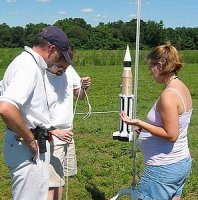
Top Left: Bruce Sexton and Jess help me get the Saturn and PVC Spider ready (Tim Callender photo).
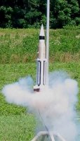
Right: The Saturn Test Model flies under the power of two D12-3’s and two C11-0’s before its spectacular crash (Tim Callender photo).
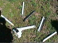
Bottom Left: The Saturn booster shortly after the crash (still image from video).
Second Flight of 2-Stage Test Model
(Fathers’ Day 6-19-05)
The second flight testing the RC Gear took place one year after the crash. There were several design changes after the first staged flight, including moving the RC-arming switches and changing the method of booster chute deployment from booster ejection charge deployment to deployment coupled with staging (the new deployment method required packing multiple chutes between the upperstage fins and was subsequently deemed too complex to prep consistently or comfortably). With the addition of an elaborate pre-launch checklist, the flight went off almost without a hitch. The Saturn boilerplate launched, staged, deployed all its chutes, and was recovered with all objectives fulfilled.
The only significant issue was unintended separation of the second stage fin-unit/motor mount at RC-activated ejection (this was remedied by changing the location of the anchoring screws and by strengthening the fin unit’s structure). An additional seemingly minor issue was some waviness in the upperstage flight profile (possibly due to severe coning). At the time I considered this to be the result of using a B6 motor in a heavy upperstage and/or due to friction issues caused the combined staging/chute deployment event. However, photos and video of the NARAM-50 flight (that did not deploy chutes during staging) show immediate post-burnout instability after a brief, but nominal flight of the upperstage. Thus the addition of pop-out fins will be needed for any future SA-5 model flights.
Continue to Page 3… 2008 Model Overview


