Project Page Contents:
1. Introduction & Early Test Flights
2. Second Stage Development & Flights
3. 2008 Model Overview
4. 2008 Model Construction
5. NARAM-50 Flight
6. Future Modifications
This page contains photos and descriptions of various noteworthy model components, subassemblies and related items, as well as several views of the completed model at the bottom of the page (to skip to the model gallery, click here).
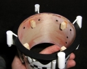
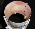
Tail Section/Motor Mount & Stuffer Tube Assembly
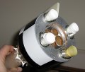
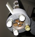
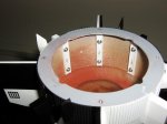
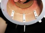
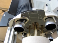
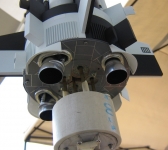
The tail section consists of three subassemblies that slide together. The scale base (A) has a split and reduced BT-80 that slides up inside the main shell (B). They are fastened together by four external #2 socket head cap screws that also serve as scale details. The motor mount/stuffer tube (C) form a single subassembly that is glued together permanently so as to maintain consistent alignment (critical for proper fit of the tank tubes).
 Part C then slides down into the reduced BT-80 sleeve of part A and is bolted to an anchor ring with T-nuts in part A using #2 screws. Two #2 threaded rods from part C protrude out of the bottom of the assembled unit for motor retention.
Prior to construction of part A, the motor mount/stuffer subassembly is aligned and glued together with the aid of a jig consisting of a long section of BT-80 with four “windows” cut near one end. The split BT-80 sleeve from part A is also used inside one end of the jig (see windows drawn in righthand sketch). The windows allow visual alignment of the stuffer tube and motor mount, and provide access for applying glue in small amounts.
Casting Hollow Fins
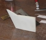
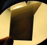
 The four smaller “stub fins” of the model were cast as solid pieces with some resin drilled out for weight reduction, but he larger fins were made lighter by casting them around a hollow folded cardstock “wedge” that is placed in the two-sided mold. The corners and joints of the wedge were sealed with CA, as were some of the flat surfaces near the leading edge of the fin (to prevent a bubbles from forming in various shallow parts of the casting). A strip of cardstock at the leading edge (see left photo) and two small 1/8″ thick bits of balsa at the root edge (see upper right photo) were added to keep the wedge in place during casting.
After each hollow casting was firm enough to handle (not completely cool), I had to drill a vent hole into the hollow space through the root edge. This prevented the fin from becoming bloated on the sides. I’m not quite sure why this is happens, but I have a pretty good guess… when a hollow casting is made, the resin gets hot (fast-curing Polytek Easyflo 60), while the air inside the hollow wedge stays relatively cool. As the casting cools, it contracts around the already cool air which presses outward on the not-yet-hardened sides of the fin… so that’s my hypothesis.
This technique yielded variable results for me and is worth some further experimentation. I also attempted to make the stub fins hollow using the same technique, but for whatever reason, I did not have very much success.
Fin Attachment
The polyurethane resin fins were each attached through the plywood wall using #2 self-tapping screws and washers (the hollow fins have a 1/8″ thick root edge that the screw threads can ‘bite’ into). Styrene I-beams were used between the plywood skin and screw heads as a means to conform the round plywood skin to the flat root edges of the fins, eliminating small gaps and providing a firmer anchor than the plywood skin alone.
A Few Interesting Tail Section Details…
Corrugation Troubles and an Odd Solution
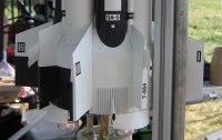 The eight sets of corrugations were planned as resin castings that were to be painted prior to applying them to the slick Monokote skin using Scotch 463 double-sided tape. In fact I had several castings that had been made in 2005 that I had applied as planned. Then all hell broke loose as some of the corrugations began to peel up after a few days (after sitting for three years and painting, the castings had a concave shape to them, but I thought the thin “backing” would be flexible enough for the tape to work, but I was wrong). I attempted to re-seat them by wrapping paper and masking tape around the finless base for a day or two. This seemed to work at first, except that some of the paint and primer appeared a bit squished and distorted from the tape pressure. Then they started peeling up again. Then I noticed that my castings were slanted. I had applied them correctly, but the pattern itself had a definite “lean” to it–in other words, I had screwed up the master pattern, but had not noticed it for a long time. I carefully peeled those annoying things off the model and brainstormed some solutions (time was a major factor at this point).
Ideally I would simply construct a new master and recast all of them (this time pre-curling the pieces before they completely hardened). But I came up with an odd solution that yielded acceptable results in the time remaining. The resulting part consisted of four layers of material (from top down):
Styrene Strips (corrugations)
Trim Monokote (facing up)
Scotch 463 Double-Sided Tape
Trim Monokote (facing down)
The top layer of Monokote holds the corrugations on. While installing the strips, I was able to keep the unused portions of Monokote unexposed by covering with a loose piece of backing material and shifting it over as I progressed. After installing all the strips (not yet cut to final length), I brush-painted a coat of Future Floor Finish over the entire piece to de-sticky the sticky backing. After shaping and priming, the pieces were each applied to the model with the aid of soapy water, then painted in place on the model.
Heat Shield Panel Lines
The heat shield panel lines are simulated by scoring the surface of the plate (plywood with a layer of CA-soaked paper) to make slight recesses. The part is then primed, sanded smooth, then coated in Duplicolor Chrome. The entire surface is wet sanded with very fine sandpaper, changing the panels to a dull metalic gray and leaving the recesses shiny chrome.
Engine Nozzles (outboard positions only)
The simulated engine bells were roto-casted by hand in a simple one-piece mold.
Engine Skirts (fairings below Stub Fins)
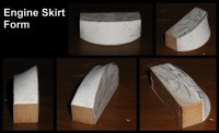 The engine skirt fairings are .02″ thick styrene heat-formed over a solid master pattern, then trimmed/sanded to shape using the master pattern as a jig. The skirts were stiffened by gluing plastic strips behind them to help them hold their shape. Two pieces of .015″ music wire were glued behind either side of each skirt, protruding above the skirts about 3/8″ so as to slide inside holes the base of the model to improve the glue joint. The fit between the skirts and the detailed base plate was tight in some places and needed a lot of adjustment to a couple of the skirts (as well as some adjustment to the plywood plate) for a proper fit.
The master pattern/form was made from spruce strips, 1/64″ plywood, and Sculpey polymer clay. It was originally intended as a master pattern for making a rubber mold for some sort of a fiberglass (or resin) casting. The sculpted clay proved more difficult to get a perfectly smooth finish than I had anticipated, so I experimented with heat-forming styrene and found a technique that worked pretty well. Notice the extra markings on the printed paper parts of the pattern. These were planned locations of air scoop details that I did not have time to implement.
Tank Tube Design
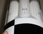
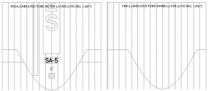 The scale fuel and LOX tanks for this model were designed to be flush-mounted on top of the conical shroud of the tail section, unlike the traditional method of recessing tubes into a shroud with “scalloped” cut-outs, as used in most kits. Thanks to USA Spacemodeling team scale modeler Jay Marsh for recommending this concept. For further discussion of the merits of this method, click here. The tubes themselves were to be made of three layers of gummed paper tape, made in the same fashion as those on the first boilerplate. I had originally planned to use a slip-on fiberglass template to cut the necessary “mitered” shape into each tank.
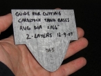
After some mixed results with my first fiberglass template, I devised a plan to make the mitered tank bases from two layers of cardstock with the inside layer offset slightly upward (to give the tank a nice sharp single-layer edge). Note that the average of the diameters [(O.D. + I.D.)/2] was used to account for the thickness of material. The two layers would first be glued together flat, then curled and joined. The completed cardstock section would then be coupled to the main paper tube. See photos below for more details. Note also the slight imperfect gap under the tanks in the lower right photo…once the fins are in place this view of the gap is masked. Also, the normal viewing angle is such that imperfections are generally hidden from view.
Tank Tube Mounting System
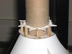
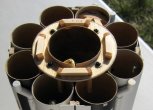 As with many other things on this model, the tanks are made to be replaceable. They are positioned using three star-shaped centering rings and are retained in position against the rings and conical shroud by eight (upward-facing) 3/16″ x 1/8″ basswood strips at the top of the cone (see left photo) and eight identical (downward-facing) strips at the top of the booster stuffer tube (see right photo). The top retaining strips are mounted to a single centering ring that is bolted in place at the top of the booster.
Interstage
The Interstage is constructed of a single layer of 1/64″ plywood, a balsa/ply centering ring, and a styrene conical shroud. All details are painted resin castings with Monokote strips for added realism on the hydrogen vent lines. The roll pattern was printed on an ALPS printer and applied in two sections to the monokoted tube surface using the soapy water method. Several applications of Walthers Solvaset were required to get rid of all the wrinkles in the thin decal material.
The photos below show the assembly inside and out. Note how shiny white Trim Monokote looks prior to applying the Testors Acryl Flat clear coat, as well as the extensive use of #2 screws for detail-mounting. The small round camera pods are the only details glued in place. The photos do not show the replaceable (sacrificial) coupler tube that protects the Interstage from upperstage exhaust.
S-IV Stage/Instrument Unit/Payload
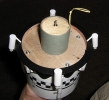
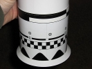
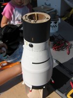 The model’s 2nd stage was also made primarily of plywood, both for the cylindrical sections, as well as the conical adapter. The RC gear and other internal parts that slide into this plywood shell are discussed in more detail on Saturn Project Page 2. In the photo to the right, note in particular the three RC arming switches that protrude from the top of the stage and the kevlar shock cord that is anchored outside the chute compartment. The cylindrical sections are covered in Trim Monokote while the taper is painted white. The black markings are ALPS-printed decals. The Instrument Unit round recesses were [vaguely] simulated by holes cut in the Monokote (a more realistic representation would appear in a future version).
Jupiter Nose Cone
The three sections of the Saturn’s nose cone are held together by a center-mounted threaded rod and a nut. The top section is a roto-casted resin piece that contains an ounce of lead nose weight plus epoxy. The lower two sections are made from 1/64″ plywood rolled into a cone. Note the three oval holes in the bottom centering ring that accommodate the protruding RC-arming switches. There is also a separate T-nut (off-center) that allows the nose cone to be bolted to the side of the transport box. You can also see the gray plastic channel that fits over the 2nd stage’s shock cord.
Photos of Completed SA-5 Model
Various close-ups of SA-5 Saturn I taken by Josh at NARAM-50
Details that I wanted to include–but couldn’t due to lack of time or some other good excuse…
- Holddown Structures (under all eight fins)… These structures are fairly obvious (yet tiny even at 1:59 scale), so I was quite disappointed to not be able to add these to the fins. However, I do have some ideas how I might more easily incorporate them into future fin designs.
- Spherical Recessed hatch covers on Instrument Unit… As of November 2008, I already have developed a solution for this one!
- Fuel Tank Vents… I included the LOX vents at the top of the white tubes (obvious in photos), but I didn’t get to make the LH2 vents on the black tanks (located just beyond the upper right corner of the white stripe on each black tank).
- Propellant Dispersion Charges on all 8 tanks… In photos you can see a red cable-like object running most of the length of the tanks and positioned to the left side of the white stripe on the black tanks, and similarly positioned on the white tanks.
- Fuel and LOX drain connection (two total)… These were low priority, and I did not have any good photo data for them this time around.
- Inboard Engine Nozzles… I’m working on a possible solution, but it will take some R&D.
- Air Scoops on the engine skirts… Don’t get me started.
- Rivets and welds on the tanks and tail section… Ditto.
Adjusting the Saturn’s CG and Final Launch Weight
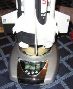 I was seriously concerned that the addition of needed nose weight in combination with the added resin details (the earliest model was flown with several details omitted) would end up severely overweight. Fortunately, we only needed to add 1 oz. of lead/epoxy to get the center of gravity where we wanted it, so that with chutes and motors installed, the model ended up weighing 34.9 oz. at liftoff. I was very pleased that my weight reduction techniques offset the added weight of the details and several metal screws by the time all was finished.
Recovery System for the Saturn I
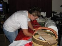 Teammate Jess made all the Saturn’s parachutes (for every boilerplate flight through the NARAM-50 flight). For the NARAM-50, we used four polyester parachutes with 12 shroud lines each, in the following sizes for each corresponding stage:
- Nose Cone: 15″
- 2nd Stage: 30″
- Interstage: 12″
- 1st Stage: 40″
Both the booster and upperstage shock cords were anchored outside of their parachute compartments. This required notching the Interstage’s coupler tube as well as the shoulder of the 2nd stage nose cone to accommodate the thickness of a kevlar line running down the side of each chute compartment.
Saturn Launch Rail System
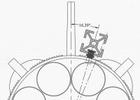 For the initial painted boilerplate flights through the 2005 final boilerplate flight, we employed a 1″x1″ 80/20 aluminum rail (1/4″ slot) mounted to a PVC launch pad base. “Standard” size rail buttons were mounted on the model, but had to be centered between fins (22.5° from Fin #I) to accommodate the width of the rail. The buttons also had to “stand off” a more-than-ideal distance from the body due to a conflict with the engine skirt fairings. To solve this design conflict, I acquired a 20mm 80/20 rail (~3/16″ slot) that would allow me to offset my rail button position (≈16.4° from Fin #I), keeping them close to the body and out of the way of the engine skirts. I was able to employ a LOX vent detail hole at the top of a tank tube as my mounting location for the upper button. The rail buttons were pieced together from various nylon washers and standoffs, and were mounted to the rocket with #4 screws and T-nuts.
Continue to Page 5… NARAM-50 Flight
