Project Page Contents:
1. Introduction & Early Test Flights
2. Second Stage Development & Flights
3. 2008 Model Overview
4. 2008 Model Construction
5. NARAM-50 Flight
6. Future Modifications
During the construction of the 2008 model, I struggled with the desire to make improvements to the model’s design that would be too time consuming. But now that the model has flown, I can plan those changes that may show up in future models. . .
Spherical Recesses in the Instrument Unit
At NARAM-50 Peter Alway and I discussed several of the details that we did not do on our respective SA-5 models (Peter’s model is in 1:69 scale). On both our models, the four spherical recesses of the Saturn I’s Instrument Unit were approximated without their distinctive spherical shape.
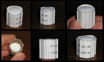
Shortly after NARAM I began brainstorming some ways I could simulate this detail. I decided on a one piece casting that will fit through a hole in the body tube wall. After my third attempt to create the master pattern, I took some photos of the part (see photos to the right). For a comparison with the real thing, go here (external link).
The part will need to be primed and sanded smooth before pouring the rubber for the mold. The final casting will be much shallower than the pattern, perhaps no more than 1/4″ total height.
The basics of the master pattern:
 The body is a two-layer wrap of cardstock (close in size to a BT-20). The internal tube is for reinforcement only. The spherical disk is .02″ styrene heat-formed over a 1.75″ wood doll head, then cut to the proper diameter with a circle cutter, using the back of the blade to score the cut. The spherical disk is inserted snugly into a hole in a flat scrap of .02″ styrene, then CA’d from the back. The disk/scrap combo was then glued on top of an additional .02″ styrene layer for reinforcement (with a small hole cut in the middle for glue access), then cut down to the final diameter for proper fit within the cardstock tube. The internal brown tube is for reinforcment, but with a nice square cut at the end it also aided in positioning the styrene unit before final gluing.
The plan is to have an hole cut-out in a 2.6″ dia plywood or fiberglass tube (same size as BT-80). The outer lip of the detail should sit flush with the outer layer of tube and will need some sort of filler at the joint. The plastic strips on the master pattern form ‘stops’ that will help position the part (and since they’re narrow, they should be easy to adjust on the final castings). Four of the longitudinal lines are scored and will show “valleys” in the casting that help orient the part visually before gluing.
For a more typical 1:70 scale model, a 1.5″ dia wood sphere or doll head would work. Bear in mind that I’m using diameters larger than Peter’s drawing shows due to some Instrument Unit data and a (low-res) photo I have come across. If anyone wants more information on this, feel free to send an email. I may eventually post that here.
I will add further information as things progress and as time allows…
