PART 1 – Logistics of the Clustered Tanks
PART 2 – How to Draw the Tank Fairing
PART 3 – How to Draw a Mitered Tank Template
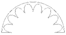
As previously stated in Part 1, the traditional method for transitioning from the cluster of 8 tank tubes to the lower tail section is to use a conical shroud with “scalloped” cut-outs that fit around the tanks. Since many modelers will need to compromise true-scaleness of tube sizes for various reasons, most models will require drawing this fairing from scratch. The following page will show how one might go about “developing” this part in a CAD or other drawing program (it also works using paper and pencil with the correct drawing tools).
UPDATE: If you don’t want to draw your own, you can use Steve Humphrey’s Transition Maker.
Click on any small drawing for a larger version. Feel free to print the larger drawings as a visual aid.
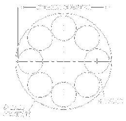 Before you can begin…
You need at least three pieces of information before you can begin:
- Tail section outside diameter
- Tank tube outside diameter
- Tank spacing (typically the outer diameter of the tank cluster)
These dimensions will vary due to scale and the parts used. If part sizes are “fudged” in any way, some time may need to be spent arranging the parts in CAD to optimize the layout, minimizing variation from true scale as much as possible. When the layout is finally settled, you can move on to step 1.
NOTE: Many of the following drawings have been simplified for clarity. Superfluous overlapping lines and arcs have been cut to make the drawings appear cleaner than the original. Also, note the line color changes from each step to the next. Typically (but not always), red denotes current drawing activity and gray shows items that were previously drawn . Some lines (new and old) remain black for clarity.
 Step 1
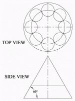
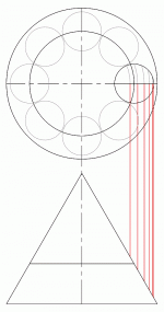
Begin by drawing the top view as shown using known dimensions. Add an additional circle that intersects the center points of the tank tubes (this will serve as the highest point of the fairing).
The side view is developed using the top view and is aligned directly beneath the top view. The triangle’s sides are 60° relative to the base.
 Step 2
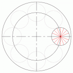
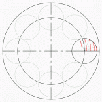
Separate the righthand tank tube into 16 slices. One way to accomplish this is to draw a single line of a different color, then use the Radial-Copy tool.
 Step 3
Using the center points of the large circles, draw concentric circles or arcs (I use the Circle Center and Point tool) through the intersection of the lines (from Step 2) and the tank tube, making sure that the arcs intersect the horizontal tank centerline. Notice that not all segments are used to draw the arcs; only one arc left of the inner circle is drawn (though I sometimes draw two).
 Step 4
Draw vertical lines (I typically use the Parallel Line tool) through the intersection of the arcs (in Step 3) and the horizontal tank centerline, down to intersect the right side of the triangle. Also draw a line down from the right-most edge of the tank.
 Step 5
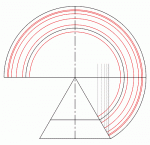
Copy the triangle and vertical lines (from Step 4) to an unused part of the workspace. Using the top vertex of the triangle as a center point, draw concentric circles or arcs through the intersections created in Step 4.
Draw circles or arcs (of a different color) through the lower right corner of the triangle and the right endpoint of the line above it.
Draw a horizontal line through the top vertex of the triangle, extending to the outer edges of the the arcs or circles. You may want to “trim” any overlapping arcs below the new line (or copy the drawing and trim it elsewhere, just-in-case). This will form the body of the final fairing template.
 Step 6
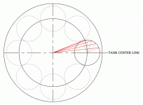
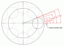
Return to the Top View and draw line segments from the center of the large circles to the end points of the line segments from Step 2.
 Step 7
Measure the angles of the lines created in Step 6 (relative to horizontal) and record them in order (I usually measure the angles’ precision to 3 or 4 decimal places).
 Step 8
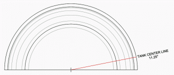
Starting from the center point of the arcs created in Step 5, draw a line 11.25° to the outermost circle. This will be the center line of the tank cutout.
 Step 9
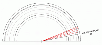
Take the angle measurements that were recorded in Step 7 and divide their values in half. Use the Radial-Copy tool to copy the tank center line five separate times, using the new angle values to space the new lines.
The lines could also be drawn individually with the Line tool by adding 11.25 to the halved angle values.
 Step 10
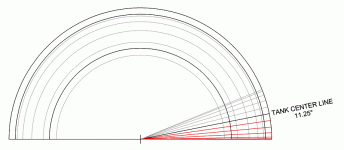
Using the tank center line as an axis, Mirror-Copy the five lines created in Step 9.
 Step 11
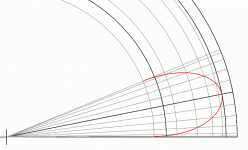
Use the Bezier tool (Spline by Fit Points should work also) to connect the intersections of the lines as shown. Only the innermost black (left) and outermost black (right) arcs are ignored in this step.
 Step 12
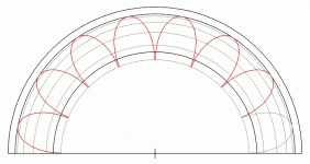
Use the Radial-Copy tool to make a total of 8 curves around center point, spacing them at 22.5°.
 Step 13
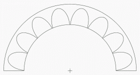
Delete all concentric arcs except the outermost and innermost black arcs. Then trim everything that overlaps the inner black arc. The shroud is now complete.
 Visual Summary
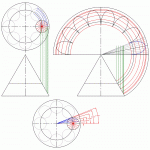
The following is a drawn summary that may help you to visualize the development process:
Continue to Part 3. . . How to Draw a Mitered Tank Template
