SA-5 Saturn I (1:59) Page 4

2008 Model Construction

This page contains photos and descriptions of various noteworthy model components, subassemblies and related items, as well as several views of the completed model at the bottom of the page (to skip to the model gallery, click here).


Tail Section/Motor Mount & Stuffer Tube Assembly

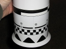
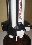
The tail section consists of three subassemblies that slide together.  The scale base (A) has a split and reduced BT-80 that slides up inside the main shell (B).  They are fastened together by four external #2 socket head cap screws that also serve as scale details.  The motor mount/stuffer tube (C) form a single subassembly that is glued together permanently so as to maintain consistent alignment (critical for proper fit of the tank tubes).

tailsketch Part C then slides down into the reduced BT-80 sleeve of part A and is bolted to an anchor ring with T-nuts in part A using #2 screws.  Two #2 threaded rods from part C protrude out of the bottom of the assembled unit for motor retention.

Prior to construction of part A, the motor mount/stuffer subassembly is aligned and glued together with the aid of a jig consisting of a long section of BT-80 with four “windows” cut near one end.  The split BT-80 sleeve from part A is also used inside one end of the jig (see windows drawn in righthand sketch).  The windows allow visual alignment of the stuffer tube and motor mount, and provide access for applying glue in small amounts.


Casting Hollow Fins

hollowfin2 The four smaller “stub fins” of the model were cast as solid pieces with some resin drilled out for weight reduction, but he larger fins were made lighter by casting them around a hollow folded cardstock “wedge” that is placed in the two-sided mold.  The corners and joints of the wedge were sealed with CA, as were some of the flat surfaces near the leading edge of the fin (to prevent a bubbles from forming in various shallow parts of the casting).  A strip of cardstock at the leading edge (see left photo) and two small 1/8″ thick bits of balsa at the root edge (see upper right photo) were added to keep the wedge in place during casting.

After each hollow casting was firm enough to handle (not completely cool), I had to drill a vent hole into the hollow space through the root edge.  This prevented the fin from becoming bloated on the sides.  I’m not quite sure why this is happens, but I have a pretty good guess… when a hollow casting is made, the resin gets hot (fast-curing Polytek Easyflo 60), while the air inside the hollow wedge stays relatively cool.  As the casting cools, it contracts around the already cool air which presses outward on the not-yet-hardened sides of the fin… so that’s my hypothesis.

This technique yielded variable results for me and is worth some further experimentation.  I also attempted to make the stub fins hollow using the same technique, but for whatever reason, I did not have very much success.


Fin Attachment

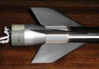
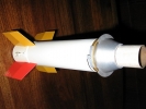
tailsection2 tailsection1

The polyurethane resin fins were each attached through the plywood wall using #2 self-tapping screws and washers (the hollow fins have a 1/8″ thick root edge that the screw threads can ‘bite’ into).  Styrene I-beams were used between the plywood skin and screw heads as a means to conform the round plywood skin to the flat root edges of the fins, eliminating small gaps and providing a firmer anchor than the plywood skin alone.


A Few Interesting Tail Section Details…

Corrugation Troubles and an Odd Solution
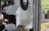
tail_details The eight sets of corrugations were planned as resin castings that were to be painted prior to applying them to the slick Monokote skin using Scotch 463 double-sided tape.  In fact I had several castings that had been made in 2005 that I had applied as planned.  Then all hell broke loose as some of the corrugations began to peel up after a few days (after sitting for three years and painting, the castings had a concave shape to them, but I thought the thin “backing” would be flexible enough for the tape to work, but I was wrong).  I attempted to re-seat them by wrapping paper and masking tape around the finless base for a day or two.  This seemed to work at first, except that some of the paint and primer appeared a bit squished and distorted from the tape pressure.  Then they started peeling up again.  Then I noticed that my castings were slanted.  I had applied them correctly, but the pattern itself had a definite “lean” to it–in other words, I had screwed up the master pattern, but had not noticed it for a long time.  I carefully peeled those annoying things off the model and brainstormed some solutions (time was a major factor at this point).

Ideally I would simply construct a new master and recast all of them (this time pre-curling the pieces before they completely hardened).  But I came up with an odd solution that yielded acceptable results in the time remaining.  The resulting part consisted of four layers of material (from top down):

Styrene Strips (corrugations)
Trim Monokote (facing up)
Scotch 463 Double-Sided Tape
Trim Monokote (facing down)

The top layer of Monokote holds the corrugations on.  While installing the strips, I was able to keep the unused portions of Monokote unexposed by covering with a loose piece of backing material and shifting it over as I progressed.  After installing all the strips (not yet cut to final length), I brush-painted a coat of Future Floor Finish over the entire piece to de-sticky the sticky backing.  After shaping and priming, the pieces were each applied to the model with the aid of soapy water, then painted in place on the model.

Heat Shield Panel Lines

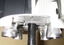
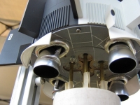
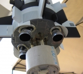
The heat shield panel lines are simulated by scoring the surface of the plate (plywood with a layer of CA-soaked paper) to make slight recesses.  The part is then primed, sanded smooth, then coated in Duplicolor Chrome.  The entire surface is wet sanded with very fine sandpaper, changing the panels to a dull metalic gray and leaving the recesses shiny chrome.

Engine Nozzles (outboard positions only)

The simulated engine bells were roto-casted by hand in a simple one-piece mold.

Engine Skirts (fairings below Stub Fins)
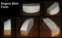
eng_skirt_form The engine skirt fairings are .02″ thick styrene heat-formed over a solid master pattern, then trimmed/sanded to shape using the master pattern as a jig.  The skirts were stiffened by gluing plastic strips behind them to help them hold their shape.  Two pieces of .015″ music wire were glued behind either side of each skirt, protruding above the skirts about 3/8″ so as to slide inside holes the base of the model to improve the glue joint.  The fit between the skirts and the detailed base plate was tight in some places and needed a lot of adjustment to a couple of the skirts (as well as some adjustment to the plywood plate) for a proper fit.

The master pattern/form was made from spruce strips, 1/64″ plywood, and Sculpey polymer clay.  It was originally intended as a master pattern for making a rubber mold for some sort of a fiberglass (or resin) casting.  The sculpted clay proved more difficult to get a perfectly smooth finish than I had anticipated, so I experimented with heat-forming styrene and found a technique that worked pretty well.  Notice the extra markings on the printed paper parts of the pattern.  These were planned locations of air scoop details that I did not have time to implement.


Tank Tube Design
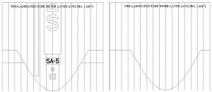
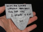
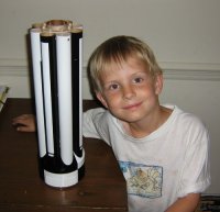
TankLayout_07 The scale fuel and LOX tanks for this model were designed to be flush-mounted on top of the conical shroud of the tail section, unlike the traditional method of recessing tubes into a shroud with “scalloped” cut-outs, as used in most kits.  Thanks to USA Spacemodeling team scale modeler Jay Marsh for recommending this concept.  For further discussion of the merits of this method, click here.  The tubes themselves were to be made of three layers of gummed paper tape, made in the same fashion as those on the first boilerplate.   I had originally planned to use a slip-on fiberglass template to cut the necessary “mitered” shape into each tank.

After some mixed results with my first fiberglass template, I devised a plan to make the mitered tank bases from two layers of cardstock with the inside layer offset slightly upward (to give the tank a nice sharp single-layer edge).  Note that the average of the diameters [(O.D. + I.D.)/2] was used to account for the thickness of material.  The two layers would first be glued together flat, then curled and joined. The completed cardstock section would then be coupled to the main paper tube.  See photos below for more details.  Note also the slight imperfect gap under the tanks in the lower right photo…once the fins are in place this view of the gap is masked.  Also, the normal viewing angle is such that imperfections are generally hidden from view.


Tank Tube Mounting System
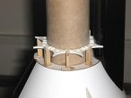
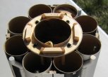
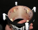
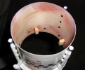
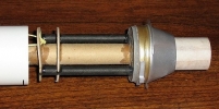
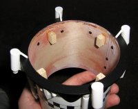
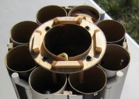
tank_aft2 tube_retain As with many other things on this model, the tanks are made to be replaceable.  They are positioned using three star-shaped centering rings and are retained in position against the rings and conical shroud by eight (upward-facing) 3/16″ x 1/8″ basswood strips at the top of the cone (see left photo) and eight identical (downward-facing) strips at the top of the booster stuffer tube (see right photo).  The top retaining strips are mounted to a single centering ring that is bolted in place at the top of the booster.


Interstage

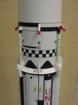
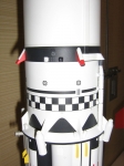
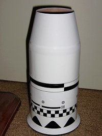
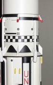
The Interstage is constructed of a single layer of 1/64″ plywood, a balsa/ply centering ring, and a styrene conical shroud. All details are painted resin castings with Monokote strips for added realism on the hydrogen vent lines.  The roll pattern was printed on an ALPS printer and applied in two sections to the monokoted tube surface using the soapy water method.  Several applications of Walthers Solvaset were required to get rid of all the wrinkles in the thin decal material.

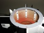
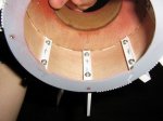
The photos below show the assembly inside and out.  Note how shiny white Trim Monokote looks prior to applying the Testors Acryl Flat clear coat, as well as the extensive use of #2 screws for detail-mounting.  The small round camera pods are the only details glued in place.  The photos do not show the replaceable (sacrificial) coupler tube that protects the Interstage from upperstage exhaust.


S-IV Stage/Instrument Unit/Payload
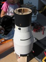
siv_payload1 The model’s 2nd stage was also made primarily of plywood, both for the cylindrical sections, as well as the conical adapter.  The RC gear and other internal parts that slide into this plywood shell are discussed in more detail on  Saturn Project Page 2.  In the photo to the right, note in particular the three RC arming switches that protrude from the top of the stage and the kevlar shock cord that is anchored outside the chute compartment.  The cylindrical sections are covered in Trim Monokote while the taper is painted white.  The black markings are ALPS-printed decals.  The Instrument Unit round recesses were [vaguely] simulated by holes cut in the Monokote (a more realistic representation would appear in a future version).


Jupiter Nose Cone

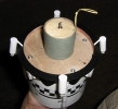
The three sections of the Saturn’s nose cone are held together by a center-mounted threaded rod and a nut.  The top section is a roto-casted resin piece that contains an ounce of lead nose weight plus epoxy.  The lower two sections are made from 1/64″ plywood rolled into a cone.  Note the three oval holes in the bottom centering ring that accommodate the protruding RC-arming switches.  There is also a separate T-nut (off-center) that allows the nose cone to be bolted to the side of the transport box.  You can also see the gray plastic channel that fits over the 2nd stage’s shock cord.


Photos of Completed SA-5 Model

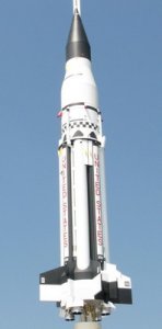
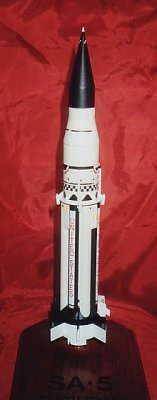
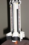
Various close-ups of SA-5 Saturn I taken by Josh at NARAM-50


Details that I wanted to include–but couldn’t due to lack of time or some other good excuse…

  • Holddown Structures (under all eight fins)… These structures are fairly obvious (yet tiny even at 1:59 scale), so I was quite disappointed to not be able to add these to the fins.  However, I do have some ideas how I might more easily incorporate them into future fin designs.
  • Spherical Recessed hatch covers on Instrument Unit…   As of November 2008, I already have developed a solution for this one!
  • Fuel Tank Vents…  I included the LOX vents at the top of the white tubes (obvious in photos), but I didn’t get to make the LH2 vents on the black tanks (located just beyond the upper right corner of the white stripe on each black tank).
  • Propellant Dispersion Charges on all 8 tanks… In photos you can see a red cable-like object running most of the length of the tanks and positioned to the left side of the white stripe on the black tanks, and similarly positioned on the white tanks.
  • Fuel and LOX drain connection (two total)…  These were low priority, and I did not have any good photo data for them this time around.
  • Inboard Engine Nozzles…  I’m working on a possible solution, but it will take some R&D.
  • Air Scoops on the engine skirts… Don’t get me started.
  • Rivets and welds on the tanks and tail section… Ditto.

Adjusting the Saturn’s CG and Final Launch Weight
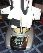
sa5_weigh2 I was seriously concerned that the addition of needed nose weight in combination with the added resin details (the earliest model was flown with several details omitted) would end up severely overweight.  Fortunately, we only needed to add 1 oz. of lead/epoxy to get the center of gravity where we wanted it, so that with chutes and motors installed, the model ended up weighing 34.9 oz. at liftoff.  I was very pleased that my weight reduction techniques offset the added weight of the details and several metal screws by the time all was finished.


Recovery System for the Saturn I
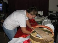
jess_chutes Teammate Jess made all the Saturn’s parachutes (for every boilerplate flight through the NARAM-50 flight).  For the NARAM-50, we used four polyester parachutes with 12 shroud lines each, in the following sizes for each corresponding stage:

  • Nose Cone:  15″
  • 2nd Stage:  30″
  • Interstage:  12″
  • 1st Stage:  40″

Both the booster and upperstage shock cords were anchored outside of their parachute compartments.  This required notching the Interstage’s coupler tube as well as the shoulder of the 2nd stage nose cone to accommodate the thickness of a kevlar line running down the side of each chute compartment.


Saturn Launch Rail System
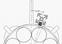
railbutton3 For the initial painted boilerplate flights through the 2005 final boilerplate flight, we employed a 1″x1″ 80/20 aluminum rail (1/4″ slot) mounted to a PVC launch pad base.  “Standard” size rail buttons were mounted on the model, but had to be centered between fins (22.5° from Fin #I) to accommodate the width of the rail.  The buttons also had to “stand off” a more-than-ideal distance from the body due to a conflict with the engine skirt fairings.  To solve this design conflict, I acquired a 20mm 80/20 rail (~3/16″ slot) that would allow me to offset my rail button position (≈16.4° from Fin #I), keeping them close to the body and out of the way of the engine skirts.  I was able to employ a LOX vent detail hole at the top of a tank tube as my mounting location for the upper button.  The rail buttons were pieced together from various nylon washers and standoffs, and were mounted to the rocket with #4 screws and T-nuts.
Continue to Page 5… NARAM-50 Flight

SA-5 Saturn I (1:59) Page 3

2008 Model Overview

Competition Model Overview

The following paragraphs discuss some of the complexities and unique attributes of the competition model that was started at the end of 2003 and finally completed in July 2008.


Model Design Complexity

The 2008 Saturn I model is the most complicated project I have ever worked on. I learned a lot of things in the process that may someday lead to other complicated projects in the future. Think about the number of different parts and details of Saturn I’s that make them complex vehicles to model at any scale–and that’s just for a static model that cannot fly. Add to that the weight and logistical constraints of successfully flying a clustered and staged model. Add to that the space requirements of radio control gear. Add to that limited chute space due to RC gear. Add to that a list of several potential designs for the internal structure–none of which are perfect. And that’s just the design phase. Add to that the degree of difficulty in construction and the need for precise fit of major surface details on multi-angled airframe surfaces without using any filler for gaps (because the parts are assembled after painting)… you will begin to picture the complexity of this project.


Custom Plywood Tubing and Tapered Shrouds

plytube While the boilerplate used a few standard tubes, the competition model employs custom tubing for all but the internal structures (stuffer tubes and motor mounts). Each of the eight scale booster tanks is made from spiral-wound gummed paper tape just like in the original boilerplate, but coupled with a small section made of cardstock at the base. There are four tubes of varying diameter constructed of 1/64″ plywood rolled against the grain. The majority of the nose cone, as well as two other major tapered body sections were also rolled from plywood (I cannot recommend this technique more highly–thanks again to John Pursley and James Duffy for this method.


Extensive Use of Resin Casting

Cast polyurethane parts were used throughout the model. The nose cone tip, fins, and most surface details are resin copies of a custom master pattern. The larger four fins are unique because they were cast with a hollow cardstock core for weight reduction.


Unusual Building Methods (Bolt-Together Construction)

Most model rockets have major components that are glued together. The 2008 Saturn is assembled such that many of the parts can be adjusted, removed, and/or replaced if necessary (though not all parts), including parts such as individual fins, certain details, and tank tubes. Several #2-56 screws (some in conjunction with blind “T” nuts) are used to hold the “loose” detail parts onto the subassemblies, or hold multiple subassemblies together. The benefits of using lightweight screws instead of glue are pretty obvious:

  • Replacing parts damaged in flight (or upgrading parts)
  • Adjusting complex parts after attachment to the mode
  • Firm attachment of some details (rather than surface-mounting
  • Ease of access to internal assemblies or electronics compartment
  • “Break-down” for easier transport (not a factor for this Saturn, which separated into multiple sections anyway)

This method has its drawbacks, too:

  • Gluing a part in it’s proper place “forever” leads to a certain peace of mind
  • Need for access to screw heads may complicate the model’s design (e.g. the Saturn I’s tail section has screws that hold 8 fins in place)
  • Bolted-on parts must be colored or painted before attachment
  • This process can slow down both design and construction
  • Will not work as well (if at all) on smaller models (but is less necessary, anyway)

Thanks to John Pursley for recommending the bolt-together method.


Unusual Finishing Methods (Paint vs. Trim Monokote)

Another unusual feature of the competition model is the extensive use of Monokote Trim film (yeah, the sticky stuff, not the iron-on stuff). John Pursley used this method on his 1:10 Vanguard and 1:12 Mercury Redstone projects (he also used iron-on Super Monokote, but I have not yet mastered the art of iron-on coverings). The finish is durable, consistent, and covers over a multitude of surface imperfections. It also provides an excellent slick surface for adhering decal material. The results are well worth the effort to experiment with this stuff. With practice one can apply it dry over some surfaces (I covered my fins this way), or over primed & sanded (smooth!) surfaces with the water w/dish detergent method (my tail section, interstage, and most of my S-IV stage were covered this way). I was able to cover my black tanks using the dry method, but I had to contend with some bubble formation due to imperfection in the “straightness” of the tubes. The following is a breakdown as to the use of primer/paint vs. Trim Monokote on the Saturn’s parts:

Monokote-Covered Parts

  • Tail Section assembly (incl. tapered shroud)
  • S-IV Stage (non-tapered surfaces only)
  • Instrument Unit/Payload Section
  • Interstage
  • Black Tank tubes & white band
  • All fins (except for narrow leading edge)
  • “Flat” or Low-Profile Surface Details

Primed and Painted Parts

  • S-IV Stage (tapered surfaces only)
  • Nose Cone
  • White Tanks
  • Rear of Tail Section
  • Most Surface Details
  • Scale Engine Nozzles

Unusual Teammates

This project would not have been successful without the support provided by my teammates.  Jess, along with her unending encouragement, poured rubber molds, made castings, sprayed and sanded primer, made all the parachutes used in the test models and competition model. She even designed and built the the transport box that we used to carry the model to NARAM-50. Kevin Johnson encouraged and nagged me until I finished the model. He helped with the pre-flight prep at NARAM-50 by charging batteries, packing chutes, etc… and stayed up late with me one night to help me get the CG correct. Thanks, Kevin!


Continue to Page 4… 2008 Model Construction

SA-5 Saturn I (1:59) Page 2

Second Stage Development & Flights

RC Staging & Ejection

In early 2004 I decided to add a backup recovery system for the final version of the model. After several email conversations with John Pursley, I decided to go with RC-activated recovery. Since I was going to make the investment in the RC gear, I decided to go ahead and also use RC to simulate S-IV stage ignition so as to acquire as many mission points as possible during competitive flight.

The onboard ejection/staging system basically consists of the radio receiver (Rx), two 50 mAh or 150 mAh 4.8v battery packs (one for the Receiver and one for the igniters), two relay switches, a single mercury switch, a few on-off toggle switches, and a Revolution base-loaded antenna. The mercury switch acts as an on-ground/in-flight safety switch so that no RC glitches can cause premature ignition or recovery deployment–at least until motor burnout.

2nd Stage ignition is accomplished via a pair of redundant Estes igniters (the NARAM-50 flight only employed one igniter), whereas parachute deployment is done with a Christmas-tree bulb ejection charge and Pyrodex P powder, using an internal piston to push out the parachute (Pyrodex ejection charges work pretty well when used with pistons–thanks to Dave Muesing for the suggestion and for the powder). Due to the fact that a section of each glass bulb is typically ejected from the rocket, a modified charge was developed for the existing bulb socket using MicroMaxx paper tubing and a single Estes igniter (this arrangement worked well in a couple of static tests, and at NARAM-50).

One major drawback of using RC Gear is its bulk. Although not overly heavy, it is rather bulky and is better suited for wider-bodied models. Nevertheless, I was able to design a layout for all the electronics so that there are no in-flight disconnects. All wiring, switches, and gear are contained within the S-IV stage alone, with none mounted in the nose cone. Mounting space is maximized by minimizing the size of the chute compartment (this has its own drawbacks). The core stuffer tube/chute compartment is a BT-60; all electronic parts fit between this tube and the airframe.
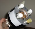
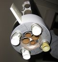
Click on the RC assembly thumbnails below for a larger view of the design. The assembly shown in the three left-hand photos was used for the second boilerplate flight and (with some minor modification) for the NARAM-50 Flight. The three right-hand photos show the addition of the 50mAh battery packs and the plywood “shell” that the RC assembly slides into. Note that a bit of plastic bag has been taped around the mercury switch for the NARAM-50 flight (just in case). Future versions of this assembly will incorporate pop-out fins for added stability. Pop-out fins had been planned for the NARAM-50 flight, but were not completed due to time constraints.

First Flight and Crash of 2-stage Test Model
(Fathers’ Day 6-20-04)

The first flight using RC for Staging/Recovery was both a failure and a success. It was a failure because the model’s recovery system did not deploy properly in either stage, nor did the second stage ignite. The first stage was destroyed, but the second stage/RC gear survived in spite of the chute not opening.
The causes of the failure are actually pretty simple. In the rush to finish prepping the model, I thought that I had installed recovery wadding under the booster chute (I had actually only installed the chute temporarily). During flight the booster ejection charge melted the polyester chute, and the booster fell tail-first and crashed. The second stage did not ignite because the igniter was pulled from its proper position as an accidental consequence of pre-flight prep. The RC-activated second stage chute did not open because it got jammed inside the open shoulder of the nose cone at the time of ejection.

The flight was a success in that the RC backup recovery activation/piston worked (even if the chute didn’t open), and it was a success because of the lessons that I learned (and the design changes they brought forth):

(1) Complex models should generally be prepped with the help of a paper (not mental) checklist. (2) Any hole in the bottom of a nose cone should always be much smaller than the size of the chute package. (3) Always do a “dry run” of the checklist to make sure there are no loopholes or crossed steps, including flaws in model design. (4) Easy access to on/off switches is critical (switches were repositioned in subsequent flights).

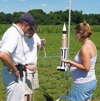
Top Left: Bruce Sexton and Jess help me get the Saturn and PVC Spider ready (Tim Callender photo).
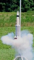
Right: The Saturn Test Model flies under the power of two D12-3’s and two C11-0’s before its spectacular crash (Tim Callender photo).
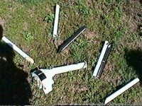
Bottom Left: The Saturn booster shortly after the crash (still image from video).


Second Flight of 2-Stage Test Model
(Fathers’ Day 6-19-05)

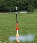
The second flight testing the RC Gear took place one year after the crash. There were several design changes after the first staged flight, including moving the RC-arming switches and changing the method of booster chute deployment from booster ejection charge deployment to deployment coupled with staging (the new deployment method required packing multiple chutes between the upperstage fins and was subsequently deemed too complex to prep consistently or comfortably). With the addition of an elaborate pre-launch checklist, the flight went off almost without a hitch. The Saturn boilerplate launched, staged, deployed all its chutes, and was recovered with all objectives fulfilled.

The only significant issue was unintended separation of the second stage fin-unit/motor mount at RC-activated ejection (this was remedied by changing the location of the anchoring screws and by strengthening the fin unit’s structure). An additional seemingly minor issue was some waviness in the upperstage flight profile (possibly due to severe coning). At the time I considered this to be the result of using a B6 motor in a heavy upperstage and/or due to friction issues caused the combined staging/chute deployment event. However, photos and video of the NARAM-50 flight (that did not deploy chutes during staging) show immediate post-burnout instability after a brief, but nominal flight of the upperstage. Thus the addition of pop-out fins will be needed for any future SA-5 model flights.

Continue to Page 3… 2008 Model Overview

SA-5 Saturn I (1:59)

Saturn I Block II (2008)

Project Overview

This series of web pages document the Meatball Rocketry Team’s SA-5 model project from its inception through its first place showing in Team Division at NARAM-50 in 2008.  It began in the Spring of 2003 (during my Peanut Scale Saturn I project) with the design and construction of a simplified sport model.  This sport model, what I call the “painted boilerplate,” became the testbed for both the PVC Spider R&D project and the eventual 2008 competition version of the model.  After the initial four flights of the boilerplate, the design and building process for the competition model took much longer than intended due to several complicating factors, such as the vast number of components involved, the larger-than-usual scale of the model, weight factors, novel construction techniques (e.g. bolt-together assembly), and being a hard-to-satisfy designer (me).  The majority of the time spent on the project involved thinking, sketching (and rethinking and re-sketching), and lots of CAD work.  Two desperate attempts to finish the project for NARAMs in 2004 and 2005 were unsuccessful, but fortunately I had two very good and patient teammates who kept encouraging me through to completion.


2003 Sport Model/Boilerplate Design

While there are obvious visual similarities between the original “painted boilerplate” and the final 2008 competition model, the differences in design and finishing are many.  For specifics on the 2008 competition model, see project pages 3 and 4.  The following text primarily discusses design and construction as it pertains to the earliest model as built and flown in 2003-2004, with little reference to the 2008 bird.


Why 1:59 scale?

I wanted to build the SA-5 in a scale that would be noticeably larger than the usual scales of 1:100 and 1:70 and have plenty of room for clustering.  I was able to come up with a combination of two standard tubes that worked out almost perfectly for 1:59 scale.  The rest would have to be rolled from scratch.  The S-IV body was constructed using a BT-100 (3.744″ dia.) purchased from Kosrox, while the scale Instrument Unit used a BT-80 (2.6″ dia.).  The Aft Skirt was rolled from a section of 1/64″ plywood (thanks to James Duffy and John Pursley for this technique).  The tank tubes were custom wound around a modified copper tube using gummed paper tape and were evenly spaced around a BT-60 core/stuffer tube using resin star-shaped rings.  The various tapered sections were cardstock reinforced with CA. The fins, nose tip, and various details (many were omitted for this model) were cast from polyurethane resin.


Cluster?  Yeah, we gotta cluster that thing!

cluster For the initial model design, I decided to utilize an 8-motor cluster, mimicking the cluster concept of the real Saturn I’s in hopes of earning some ‘mission points’ during competitive flight.  The need for safe and reliable ignition of all eight motors led to the development of the PVC Spider device. The peculiar non-scale radial arrangement of the motor mount tubes in the first boilerplate model (see lefthand photo) was chosen at first due to certain logistical concerns with the Spider.  This design was changed in subsequent models to reflect a more scale-like  arrangement of four “inboard” motors.


Scale Staging?

The initial four flights were single stage only.  Scale-like simulation of S-IV stage ignition was not attempted until the fifth flight (see Saturn page 2) as part of the testing for the competition model.  Coincidentally, this follows the real Saturn I program in which the first four flights (SA-1 through SA-4) had live 1st stages only.  It was not until the SA-5 flight that a live upperstage was added.


Model Center of Gravity (Flight Tests and 2008 Model)

Deciding on a proper balance point for the original test model was particularly difficult since the standard rocket CP/CG relationship of 1 caliber (for this model, that means at least 4.36″ between the CP and CG) causes over-stability in such shorter, fatter models as the Saturn I–a condition that (coupled with the heavy model’s relatively slow liftoff) will possibly lead to excessive weathercocking during powered flight.

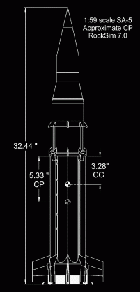
Therefore, I used RockSim version 6.0 to calculate an approximate location of the Center of Pressure, inputting an assumed solid tube in place of the eight tank tubes (you can get the latest version of RockSim from Apogee Components).  The resulting theoretical (ideal) CG location was about 2.05″ forward of the CP or 3.28″ aft of the tops of the tank tubes (see righthand drawing).  This CG location was used in all the single-stage flights as well as the first 2-stage flight and the final NARAM-50 competition flight.  This required a fair amount of clay/lead  weight ballast in the nose cone for the single-stage model, although less for the 2-stage version, due to the extra weight of the upperstage motor and RC-gear already in the model’s S-IV stage/payload sections.


9-14-2003  Initial Test Flight of the “Painted Boilerplate”

bp_prep

The original “painted boilerplate” flew on 8 C6 motors (32 oz total model liftoff weight) to an altitude between approximately 400-500 ft.  Two of the motors were C6-5’s, providing redundant ejection charges for the parachutes.  The remaining motors were C6-0’s; the propellant ‘blow-thru’ of each was vented out of the rear of the motor mount.  The model weighed 32 oz. with motors and recovery system installed.

The flight was 100% successful, and was the first live flight test of my PVC Spider prototype.  The next three flights were nearly identical in terms of performance, inspiring me with confidence in model stability and design to begin work on the competition version of the Saturn.

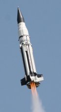
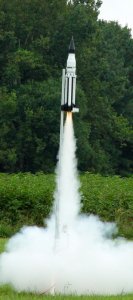
Right:   The SA-5 boilerplate model takes to the sky after successful ignition of all 8 C6 motors using my PVC Spider prototype.  (Bruce Sexton photo)
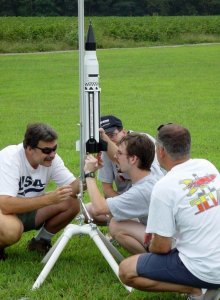
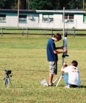
Top Left:   Bob Biedron, Pete Covell, and Scott Brown eagerly assist me in positioning the model above the PVC Spider before the first test launch.  (Bruce Sexton photo)
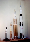
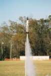
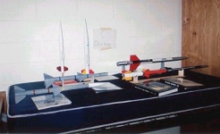
Gallery Below: The SA-5 in three scales (1:165, 1:100, 1:59) as compared with the 1:100 scale Estes Saturn V.  The largest Saturn I shown is the test model.  Note that there are many surface details (conduits, etc.) that have been left out.  The other two models are Jess’s 1:7.3 scale Iris and (to the far right) a BT-60-based (and lengthened) Mosquito upscale.  Additional photos to the right show the model during prep or launch of different single-stage boilerplate flights in 2003 (courtesy of Eric Fadely).


Related Videos


Continue to Page 2… Second Stage Development & Flights

SA-5 Saturn I (1:59) Acknowledgments

The success of the 2008 Model at NARAM-50 is due in part to a number of helpful people.  Many thanks to:

  • Jess for priming, painting, mold-making, casting, chute-manufacture, making the transport box, video recording, and lots of general assistance and encouragement;
  • Kevin Johnson for help in Spider R&D, nagging me into getting finished, and helping prep the model at NARAM;
  • John Pursley for seemingly endless emails discussing various techniques, especially RC staging/ejection, and the use of Trim Monokote;
  • Jay Marsh for his input on “mitered” tank tube construction;
  • Bob Biedron for helping out at the first boilerplate flight, for suggesting I talk to Jay Marsh, and for his input on RC gear;
  • Several SEVRA or Vikings members, such as Pete Covell, Scott Brown, Bruce Sexton, Tom Lyon, and Dan Wheeler, for helping out during boilerplate flights (Tom also helped at NARAM).  Thanks also to Eric Fadely, Bruce Sexton, and Tim Callender for taking photos during boilerplate flights.

And thank all of you who have provided images or video of the NARAM-50 flight– Bob Sanford, George Gassaway, John Cieslak, Marc McReynolds, and Mark Chrumka.

I hope I have not missed anyone…

I hope this series of Saturn I project pages will inspire many who enjoy scale model rocketry.  Thanks for viewing!


Josh Tschirhart
Nov 22, 2008

X-20 Dyna-Soar/Titan I (1:59)

"Concept Scale" Model

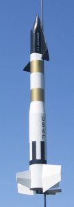
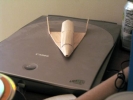
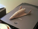
color_illus onthepad The Titan I w/ Dyna-Soar model was the first true team project for the Meatball Rocketry Team in 2005. It was based around standard ST-20 (2.042″) and BT-60 (1.637″) tubing, resulting in 1:59 scale, which is the same scale of the large Saturn I model that was in progress during that time. For a while I seriously considered modeling a proposed Saturn I/Dyna-Soar configuration in the same scale as a parallel project (an idea I abandoned for lack of data and time).

For primary scale data we referred to the Dyna-Soar book from Apogee Books and Jack Hagerty’s Spaceship Handbook. I found some additional data on the internet that helped with the Titan booster.

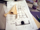
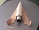
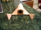
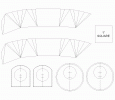
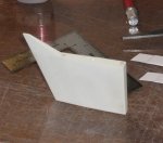
Kevin Johnson built the Dyna-Soar glider, I built the booster and applied the decals, and Jess did all the priming and painting of the booster. For my part, the most difficult component was the odd transition from the body to the glider’s base. The template used to make that part can be viewed toward the bottom of the page. This model won 1st place at ECRM-32 in Middletown, Maryland. Amazingly enough, the Dyna-Soar and booster did not come together until the night before the competition–with only minor adjustments being needed for a perfect fit (not to mention the US Air Force markings and clear coat I applied to Kevin’s glider at the hotel).

j-j-k-ds The Dyna-Soar’s glide during the two flights was less than ideal (a bit more like a spiral). It would have probably flown just fine if we had added some noseweight. Full Treatment of the construction of the Dyna-Soar glider by Kevin Johnson can be read on The Rocketry Forum here.

Dyna-Soar Extinction. . .

Long after our successful flight there was an unfortunate incident in Kevin’s apartment involving invading yellowjackets leading to Kevin jumping around leading to the model falling off his bookshelf. The fossilized remains were not worth preserving.


See below for several related photos.  Most photos are by Kevin Johnson.  Video by Jess.

SA-5 Saturn I (1:165)

Peanut Sport Scale Model -- Only 11.8" Tall!

This scale model of the SA-5 Saturn I uses cast polyurethane resin parts for the interstage shroud, fins, details, and nose.  The clustered tank tubes were custom wound around a brass tube.  The decals were drawn in TurboCAD and printed onto clear decal stock using both a laser printer and an ALPS MD-5000 printer.

The model flew on an A10-3T motor with a piston launcher.  Total weight with parachute and motor was about 2.5 oz at liftoff.  The flight ended up lower than anticipated because of premature separation from the piston, but the altitude was sufficient, nonetheless, and it won 1st place in C Division at ECRM-30 in Middletown, Maryland.

I was pleased at how the model turned out, but I built it in this scale simply because of the 30 cm length (or 2 cm diameter) constraints of the Peanut Scale event.  I would prefer to build larger models of the Saturn I.  See also the page for the 1:59 scale Saturn I project.

UPDATE:  In 2009, the little SA-5 flew at NARAM-51 to a Team Division 1st Place in Peanut Sport Scale.  Jess and I were not able to make the trip to Pennsylvania that year, so Kevin Johnson entered and flew the model for the team.

Click on an image below for a larger view.

Check Position Sensing — ddrum4

***Attention Do-it-yourselfers or anyone else who wants to see how well their pads play positionally using a ddrum4 module.***

(Posted May 22, 2001 on the Ddrums.com site by me–regarding my pads used with a Ddrum4 module)

This is really cool. I just figured it out the other day and finally tried it out earlier today. You don’t even need to use positional ddrum samples!!!

See page 19 of the ddrum4 manual where it refers to the “NOTE P” function of each channel. Apparently, the ddrum4 will send positional information via midi according to this Note P setting. Either 1,2,4 or 8 consecutive midi notes will be assigned to different positions on a pad, starting from the center and moving outward.

I used a DMPro for this experiment, triggered via midi by the ddrum4 and my Rhythm Traveler pads. For the sake of clearly differentiating the different positions, I used 8 separate chromatic samples (marimba) tuned progressively lower than each other and corresponding to 8 consecutive midi numbers (I used 38 thru 45). I assigned the ddrum4 channel to 38 and set “Note P” to 8 and hit my pad all over. I tried it with 4 and 2 as well.

If your pad is positionally accurate, you will hear the highest note in the center with progressively lower notes as you move outward and the lowest note closest to the rim.

You can probably do the same experiment with the ddrum4 only. Set up a single trigger pad and choose a default midi number. Assign seven other channels to the proper consecutive midi numbers and set up the samples so you can distinguish between positions as well as the positional order. Plug in the midi cable to both the in and out jacks of the ddrum4. Turn off the local control so you only hear what is played via midi.

Remember that not all ddrum4 samples are set up with positional sounds–thus the benefit of assigning different samples and testing via midi. This is especially helpful for people like me who are trying to convert their own pads to play like the ddrums, and for those who use samplers and want to create their own positional samples.

Josh T.


ADDED June 19, 2001 in response to a question…

Surely if you can hear positional changes in the marimba notes in the “slave” module you can also hear changes in the controller ddrum module’s drum sounds UNLESS the ddrum sounds are not set up with position sensing. I have tried many of the mega snare sounds with no sign of position capability. I’ve only tried a few toms. The 6-8 samples really (unfortunately)seem to be only for velocity. Therefore, I don’t think there’s anything wrong with your pads.

On the other hand, snare samples 219, 220, and 221 have very obvious positional changes. I can hear two different zones with 219 & 221 and three zones with 220. I do find it ironic, however, that Clavia would give us such intricate position technology (as many as 8 zones) but not include many positional samples, especially with their best samples!

Also, I started this thread before I had a successful positional experiment. Since then, both successful experiments (old ddrum pad modification and 13″ snare conversion) have only reached 98% perfection. Note P value 8 does yield 8 zones, but 1 or 2 of the 8 notes seem to get skipped over some of the time. However, values 4 and 2 seem to work flawlessly. This is probably due to the narrowness of the 8 concentric zones vs. the wideness of 2 or 4-zone positioning.

Keep this in mind: when I had my TD-8 I only noticed TWO zones–ringy and non-ringy. The ddrum4 can read 8 zones with fair precision. Just think–a 6″ radius split into 8 sections; that’s an average zone width of 3/4″.

I wouldn’t worry about your soldering. I really don’t think it’s an issue here. I’d bet that people with the default cast precision pads would experience similar subtle inconsistencies. Remember also that I had the same success with a radio shack piezo and a non-stock aluminum plate as I did with the old ddrum plate and Clavia-supplied piezo.

Josh T.

RAMTEC-10

June 15-16, 2002, Center Valley, PA

Our first Sport Scale competition. . .

Jess and I left Saturday morning at 4 am and arrived around 10:30 at the launch field. After turning in our scale models, I made a futile attempt at flying a helicopter model–shredded at ejection. Sport Scale static judging was finished by Saturday evening, and out of 16 C Division entries, my Black Brant XII was in first place, Steve Foster’s large Nike-Apache was in second, and Jess’s Iris was in third place. A nice-looking Jayhawk by Rod Schafer was fourth, and Chris Kidwell’s Redstone-like WRESAT was fifth.

Sunday morning was a little breezy, but we managed to fly without difficulty. Steve Foster attempted staging his Nike-Apache to acquire mission points, but without success. I flew my Black Brant XII single stage because of booster recovery problems encountered during staged flight at the Mick Wilkins Meet in April. It was a perfect flight and recovery on a D12-3. Jess flew the Iris, with perfect staging and a small recovery problem; the parachute for the bottom half of her upper stage didn’t deploy, but the RSO qualified the flight anyway. The result was two broken-off fins. Steve Foster later completed a second flight with successful staging, giving him enough mission points for first place (5 point lead). Darn those mission points! The Black Brant XII and Iris ended up second and third, respectively. Not bad for our first competition against several competitors.  You can see other contest results from that launch here.

Launch photos courtesy of Chris Kidwell

Black Brant XII (1:17.5)

RAMTEC-10 (2002) & NARAM-47 (2005)

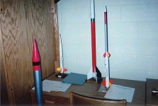
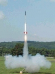
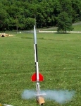
joshbbxii2 December 24, 2001, I received in the mail a set of Black Brant XII drawings and two photos from Goddard Space Flight Center. I had forgotten that I had emailed a request for scale data a month earlier. It seems that I was on NASA’s Christmas list that year. I didn’t hesitate to put the data to good use. I built and painted a fun scale model (see upper right photo) for sport flying in less than a week. It has a three-motor cluster in the booster, with one B6-0 vented to ignite a B6-4 in the upper stage. Two B6-4’s eject the booster chute. After the second flight and some cracked booster fins, I decided that B6-2’s in the booster would be safer.

josh In April I completed a fairly accurate scale model of the Black Brant XII to fly in competition (along with Jess’s Iris) at the Mick Wilkins Memorial Sport Scale Meet in Georgia on April 28th. This turned out to be a waste of a long road trip (albeit a fun one, nonetheless), since there were almost no other competitors. The updated model features more detail, along with a single D motor in the booster that operates the pistoning recovery system (this failed and had some bugs to work out).

Jess and I entered our models once again at RAMTEC-10 in Pennsylvania, June 15 & 16. We took third and second place, respectively. Because I had not yet modified the piston system, I opted not to stage, and so lost out on flight points needed for first place. For photos of ours and other Sport Scale models, go to our RAMTEC-10 page.

bbfs1 After RAMTEC I updated the fun scale model to utilize two C’s in the booster instead of 3 B’s. This method is more efficient for booster recovery and was flown twice successfully before I lost the upperstage sections in some tall trees.

In 2005, more than three years after building the Black Brant model, I was able to enter it again in competition–this time at NARAM-47 in Ohio. I had planned to enter my Saturn I model, but even after two years of on and off building, the Saturn was still not ready. I was able to finally modify the pistoning recovery system to eliminate some problematic friction, as well as incorporating dual streamers into the compartment.

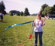
josh_ben bbxiiflight After having the highest score (in Team division) after static judging, the model flew to 1st place. The staging/recovery system worked perfectly. Had our closest competitor not been disqualified on two attempted flights, we might not have won. But it’s pretty cool that we won the national meet with a three-year-old model, not to mention one that had flown twice already.

For anyone interested in scale data on the Black Brant XII, Peter Alway has included drawings of the prototype in his Rockets of the World 2002 Supplement.

Click here for hi-res images of round 12.041 WT on our Meatball site.
Click here for a hi-res image of the first flight of the Black Brant XII on NASA’s site.

Spacemodeling Rocketry R&D CAD Design