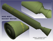
Those who enjoy modeling sounding rockets are probably familiar with the name “Nike”. The Nike M5 and M5E1 motors were originally developed for use in the boosters of the Nike-Ajax and Nike-Hercules missile systems, but they also found a place as major component in sounding rocket vehicles of various configurations. For more information on the history of the Nike missile systems, visit such sites as the Nike Historical Society, Ed Thelen’s Nike Missile Page, and others.
Nike Motor Versions (M5, M5E1, M88)
The M5, M5E1, and M88 are the three versions of Nike motor that were manufactured. According to Ed Thelen’s Nike Missile Page the M5 motor of the Nike-Ajax system was modified for use with the Nike-Hercules system (cluster of four M5E1 motors) by drilling and tapping extra holes in the motor body. This was the only difference between the M5 and M5E1 units. According to Stephen Maire, the M88 motor replaced the M5E1 in the Nike-Hercules system later in its operational life–the change in designation is probably related to the uprating of the motor’s performance and probably does not refer to any major external changes.
Nike Motor Drawings and Documents
These drawings by Bob Biedron* give some basic information on the motor itself without shroud or fins. One caveat: the Nike’s nozzle is conical and does not actually have that gradually curved shape as seen in the drawings. There is a slight discrepancy between the sketch and the line drawing regarding the location of the aft circumferential weld. The sketch predates the line drawing by several years and is verified as more accurate by comparing with other data such as nozzle shroud and screw hole positions (relevant dimension corrected on the line drawing by Josh with footnote 6/26/12. Click here for the original unedited version).
Sounding Rockets & Specified Nike Motor Designations
Official documents regarding particular sounding rocket prototypes will sometimes show a specific Nike motor designation in a drawing. Given the superficial differences between the M5 and M5E1, I do not generally think that these references denote a hard-and-fast requirement for one motor type over the other. Thus in reality one will find different rounds of similar vehicles using either type (for example, one illustration for the Nike-Tomahawk’s interstage adapter lists M5, M5E1, and M88 as all being compatible).
 Variations in Fin & Nozzle Shroud Design
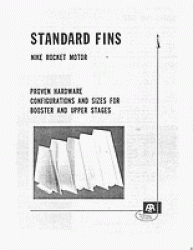
Click on the right-hand preview image for a 12-page Atlantic Research Corp. brochure (in PDF format) about different Nike Fin designs as used in various sounding rockets. The original document came from Bob Biedron’s collection.
Variations in Forward Flange
The flange at the forward end of the motor seems to vary somewhat between vehicles. Note the two variations in the Biedron drawing above. I have noticed other variations during my own visits to examine actual motors on display, such as a longer lip at the top of the flange (ranging between 1.18″ long to as long as 1.38″, as opposed to the .925″ length on the Biedron drawing–I have not yet seen in person a Nike with the lip as short as .925″).
According to John Hugh Boyd in a Scaleroc Yahoo Group message dated 6-26-04, the Nike motors used a 16″ nominal 800# ANSI standard pipe flange (a.k.a. 16 inch heavy-weight) used in pipelines and refineries (John worked for a pipeline engineering consulting firm). He suggests that the reason for the difference in flange shapes (flat conical vs. rounded ‘scoop’ scape) is due to a differences in flange manufacturer (of which there are several), and he suggests there are quite possibly even more versions in existence.
More Variations from Nominal Design
Other than the slight variations shown in the above documents, there are other notable changes between vehicles. I have usually seen the longitudinal weld in different positions than is shown in the Biedron drawing. I do not know if this is due to a subsequent change in motor design or if perhaps the variation was considered within tolerance all along.
Modifications for Sounding Rocket Flights
Depending on the type of launcher used (such as the one shown at right), extra holes may be drilled and tapped in the Nike’s forward flange and aft area (forward part of the nozzle shroud) in order to mount appropriate launch lugs. Sounding rockets that use the Nike-Ajax launcher would not require modification. The Nike Tomahawk round shown in the linked launch photo used T-shaped lugs mounted on the side of the motor opposite the standard Ajax lug position (the same forward lug design is also used on one of the Argo D-4 Javelin’s Nike stages). Rockets launching from towers typically use multiple sets of 3 or 4 launch lugs radially spaced around the airframe and may require extra holes at the forward part of the nozzle shroud (rather than the forward flange).
See below for lug drawings and one example of extra holes drilled (though not used) in the Nike’s forward flange. [Note: Aerobee 350 photo example removed 2020-05-14, as drawings obtained in 2016 show that the holes in that photo are in fact standard holes; the motor in the Aerobee 350 system is simply rotated differently than might be considered ‘typical.’]
“Unpainted” Motors and Stenciled Lettering
Unpainted motors (i.e. olive drab with yellow stenciled lettering) have sometimes been used in sounding rocket flights. Here are some photos of a Nike-Orion clearly showing the style of the stenciled lettering on an M5E1 motor with factory paint scheme.
External Links/References
Nike Historical Society
Ed Thelen’s Nike Missile Web Page
Nike Hercules page at Rocketry Online (including information by Stephen Maire)
*NOTE: All drawings by Bob Biedron are posted with his permission.


