Page Updates:
Update 7-4-2016: Important nose tip dimension finally acquired! Thank you, D.H. Meyer!
Added 11-25-2006: Aerobee 350 Project Bibliography
Drawing Update History
The Aerobee 350 Scale Data Update project began around 1991 when I discovered certain discrepancies between the drawings and photos in the original NARTS data packet. I have been in search of corrective information ever since. The 2002 NARTS update (just prior to the release of the NARTS Scale Data CD-ROM), was an attempt to correct the old discrepancies and add new information. Although the 2002 drawings were a definite improvement over the old data, too much corrective detail data had to be derived solely from photos (the update included a list of explanations for all the changes made). Since 2006 I have acquired a great deal of new information that will allow me to update the drawings again, this time much more thoroughly.
Additional Data Acquisitions
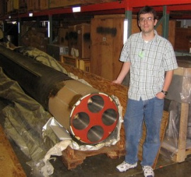
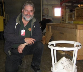
Some important detail data (and some neat B&W launch photos) have been found by researching the NASA Technical Reports Server. An old Space General brochure on the rocket was donated by Taras Tataryn. But the best data was acquired in April of 2006. A real Aerobee 350 sustainer had been planned for exhibition at the Udvar-Hazy Center at Dulles Airport in Washington D.C, but due to logistical constraints, that plan was put on hold indefinitely (Note: The vehicle is currently on display at the Aerospace Museum of California). I was able to contact a NASM curator, Frank Winter, who graciously offered me a look at the rocket still in storage at the Smithsonian’s Garber Restoration Facility. Local rocket friend (and bass player extraordinaire), Dan Wheeler, accompanied me to take measurements and several digital photos. A more in depth article on our trip to Garber was published in the Jan/Feb edition of Sport Rocketry magazine, under the title “A Visit to the Smithsonian’s Attic” (click here for a PDF version of the article).
In early 2007, I was in contact with longtime rocketeer Al Pizzo, who had many years earlier acquired Aerobee 350 data and photos from legendary rocketeer Jon Randolph. Thanks to Al, I now have several “new” photos of round 17.01 GT for the NARTS update.
Also in 2007, Peter Hughes took several photographs of an Aerobee 350 that is stored in a fenced-off location at White Sands Missile Range with the help of WSMR archivist, Doyle Piland (see related photos). It would be nice to obtain additional data on this vehicle (see link), but thanks to D.H. Meyer’s provision of nose cone data (2016–see below), this has become lower priority.
In 2013, I was contacted by Ramon Carreras who provided some nice scans of a brochures for the Aerobee 350 along with a few other Aerojet/Space General vehicles.
Important Nose Cone Data Acquired June 2016.
The ogive nose cone has a removeable tip that can be replaced with an angle of attack transducer and adapter, and thanks to D.H. Meyer, I now have data to substantiate an overall length from base to cutoff tip where the angle-of-attack transducer attaches (see caveats below). Previous attempts to derive the needed dimension (either nose length or tip diameter) using either photos and/or not-true-scale configuration drawings yielded nothing usable. This is a tremendous step forward and make it possible to complete this drawing project when time allows.
Navigating conflict between drawing dates and mission dates…
The newly acquired Space General drawings detail two similar versions of the fiberglass 5:1 ogive nose cone assembly. Drawing 1101970 (initial release 1963; Rev C, 1964) depicts a continuous ogive with integrated rounded tip and internal aluminum attachment ring at the base while drawing 1115943 (1966) details an ogive with separate nose tip and partially exposed aluminum attach ring. The later drawing specifically cites the earlier drawing number as something it is “similar to,” possibly suggesting supersession of the earlier configuration. Flight 17.01 GT (1965) predates the separate tip configuration yet has an angle-of-attack probe with adapter in place of an integrated tip, suggesting modification of the single-piece nose design (i.e., cutting off the stock nose tip, performed by either Space General or NASA). I think it’s plausible that such a pre-1966 modification may have been later integrated into the primary assembly configuration via the 1966 drawing.* Given that the 1966 drawing’s geometry appears consistent with the photos of the 1965 nose tip diameter relative to the angle-of-attack probe, I will consider the 1966 drawing’s nose tip dimensions as accurately representing the 1965 flight unless contradictory data can be found.
*Note: There could be relevant revision(s) of the 1963 drawing’s nose tip that predate the 1965 flight (the last revision I have is REV C, dated 4-30-64), but my suspicion is that the modification was treated separately from the primary assembly drawing, given certain considerations that would be difficult to articulate here.
Additional Data Sought:
I am also looking for Space General Corporation. Drawing No. SGC 70051A (used by Mark Mercer and Paul Conner for the 1973 drawing).


