PART 1 – Logistics of the Clustered Tanks
PART 2 – How to Draw the Tank Fairing
PART 3 – How to Draw a Mitered Tank Template
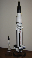
Building a Saturn I or IB model from scratch can be a tedious undertaking. Proper planning is imperative for satisfying results, but it can also be the most time-consuming part of the modeling process. In designing and building my own models, I have found a CAD program to be an indispensible tool for working with complex components such as the Saturn’s cluster of 8 fuel tanks in the S-I first stage, as well as the scalloped fairing at the rocket’s base. These parts are among the most daunting for a scratch-builder and demand special consideration early on in the design phase.
Scale S-I Tanks vs. Oversized Tanks
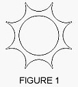
As far as I can tell, most Saturn IB kits so far have employed slightly oversized tubing to represent the S-I booster fuel tanks, allowing the modeler to glue the tubes to a round “core” with no space between the tanks. The real Saturns, however, had slight gaps between the tanks. Tank tubes (both scale and oversized) can be spaced accurately using two or three star-shaped centering rings that fit over an undersized core (stuffer) tube (Figure 1). It can be difficult to accurately cut rings as such, so I recommend using resin-casting technology to make exact copies once a suitable “master” pattern has been made. Laser cutting is another viable method for making consistent rings.
Although the difference between “scale” and oversized tanks is not very noticeable even on large models, the benefit of using the small tubes is the elimination of issues that might throw off tube alignment. Depending on the availability of proper size tubing (or the modeler’s ability to make tubing from scratch), the modeler may be forced to use oversized tubing and therefore must pay careful attention to the fit before gluing.*
*NOTE: Smaller Saturn models (under 1:100 scale) will be more sensitive to paint buildup, so keep this in mind when planning your tank layout. I had some difficulty with this on my 1:165 model; the overscale tanks ended up being slightly oval-shaped after gluing them in place around the core.
S-I “Scalloped” Tank Fairing
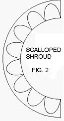
There are two methods for simulating the scalloped shroud at the base of the Saturn booster. The most widely employed method is to use a cardstock shroud with the proper elliptical cutouts to fit over the tank tubes (Figure 2). This is the method used on my 1:165 scale model. Some kits have used injection-molded plastic parts (including the current Apogee Components kit), but for scratch-builders it can be a nightmare to make a usable shroud unless one has some idea of where to begin. See Part 2 of this series for tips on drawing this part, or you can use Steve Humphrey’s Transition Maker to draw the part for you.
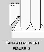
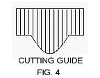
The second method is to use a standard tapered shroud and to cut out a “notch” at one end of each tank tube so that it sits on top of the shroud (Figure 3). I first heard of this method from international scale modeler Jay Marsh. I used a variation of this technique on the 1:59 scale Saturn I. “Mitering” the bottom of the tubes eliminates the difficulty of lining up a flimsy scalloped shroud over a wide base and allows for easier application of details to the tanks prior to painting and installation. It also accommodates more variation in design of the motor mount since the tank tubes do not extend into the model’s base. Jay Marsh recommends making a cutting guide using a fiberglass “master” pattern that slips over each tank tube, but a paper or cardstock wrap may be sufficient (Figure 4). It is imperative that the conical shroud be consistently shaped and aligned properly during installation so that the notched tube ends require little modification (aside from minor sanding) to fit properly. See Part 3 of this series for developing a template for cutting notches in the tanks.
NOTE: Tube cutting must be a precise operation so that all tanks will sit evenly at the bottom and the top–this is more critical for the Saturn I, as both tube ends will be visible (most Saturn IB models have tanks that extend up into the interstage body so that the tops are not visible). Mark each tank and its intended mounting location with corresponding numbers to help keep things in order. Cutting and adjusting the bottoms of all the tanks should be done before the much easier step of trimming the tops–in case any mistakes are made. A rigid, flat centering ring may be used as a visual guide during the cutting and sanding of the tops (I used the Interstage assembly as a guide during my 1:59 model project).
Continue to Part 2. . . How to Draw the Tank Fairing
