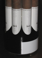
PART 1 – Logistics of the Clustered Tanks
PART 2 – How to Draw the Tank Fairing
PART 3 – How to Draw a Mitered Tank Template
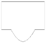 For the 1:59 scale Saturn, I used an unusual method of “mitering” the ends of the tank tubes to fit over a conical shroud rather than fitting within the shroud. The following page will show how one can develop a template for cutting this part from a tube or to make a cardstock part that can be rolled into a tube. Click on any small drawing for a larger version. Feel free to print the larger drawings as a visual aid.
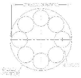 Before you can begin…
You need at least three pieces of information before you can begin:
- Tail section outside diameter
- Tank tube outside diameter
- Tank spacing (typically the outer diameter of the tank cluster)
These dimensions will vary due to scale and the parts used. If part sizes are “fudged” in any way, some time may need to be spent arranging the parts in CAD to optimize the layout, minimizing variation from true scale as much as possible. When the layout is finally settled, you can move on to step 1.
Steps 1 through 4 are the same drawing process used in Part 2, although the text descriptions may be slightly different.
NOTE: Many of the following drawings have been simplified for clarity. Superfluous overlapping lines and arcs have been cut to make the drawings appear cleaner than the original. Also, note the line color changes from each step to the next. Typically (but not always), red denotes current drawing activity and gray shows items that were previously drawn . Some lines (new and old) remain black for clarity.
Step 1
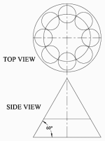
Begin by drawing the top view as shown using known dimensions. Add an additional circle that intersects the center points of the tank tubes (this will serve as the top of the cone that the tanks sit on).
The side view is developed using the top view and is aligned directly beneath the top view. The triangle’s sides are 60° relative to the base.
Note: If your model’s design requires a different cone top diameter or height (as the 1:59 scale model did), you will need to modify the drawing of your cone accordingly.
Step 2
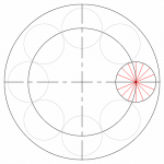
Separate the righthand tank tube into 16 slices. One way to accomplish this is to draw a single line of a different color, then use the Radial-Copy tool.
Step 3
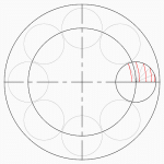
Using the center points of the large circles, draw concentric circles or arcs (I use the Circle Center and Point tool) through the intersection of the lines (from Step 2) and the tank tube, making sure that the arcs intersect the horizontal tank centerline. Notice that not all segments are used to draw the arcs; only one arc left of the inner circle is drawn.
Note: If your cone top is of a smaller relative diameter, you may need to draw additional arcs through the remaining line segments from Step 3. I do this by default, simply to give myself plenty of “wiggle-room” for potential changes in design. The important thing, however, is to make sure you have at least one arc drawn to the LEFT of the cone top circle.
Step 4
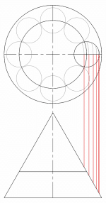
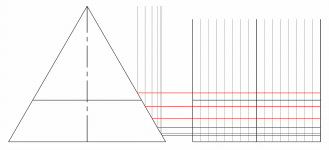
Draw vertical lines (I typically use the Parallel Line tool) through the intersection of the arcs (in Step 3) and the horizontal tank centerline, down to intersect the right side of the triangle. Also draw a line down from the right-most edge of the tank.
Step 5
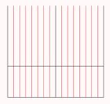
To the right of the cone side view, create the body of the tank template in line with the side view, using two vertical lines spaced apart the value of the tank tube’s circumference (pi x d or 3.14159 x diameter).
Be sure to also transfer the horizontal lines to the new template.
Step 6
Divide the template into 16 sections (in the X-direction). <—->
I use the Linear Fit Copy tool to accomplish this (fitting 17 lines in the given space creates 16 sections, as the first and last line coincide when the template is wrapped around the tube).
I typically make the center vertical line a different color to make it stand out.
Step 7
Draw horizontal lines from the intersection of the vertical lines drawn in Step 4 and the right side of the triangle.
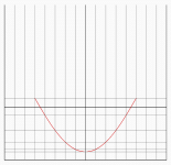
Step 8
Use the Bezier tool (Spine by Fit Points should also work) to make a curve at the intersection of the horizontal and vertical lines as shown (ignore the black horizontal lines for this step).
Note and Tip: If you have a different cone top diameter and thus have additional horizontal lines to contend with, you will need to use a different start point. In this case, it may be easier to add an extra step… Before using the Bezier tool, first draw a polyline starting at the lowest intersection (in the middle) and work backwards through each intersection to find your start point. Then use the Bezier (or Spline by fit points) tool, working from left to right as needed.
Do NOT start the Bezier tool at the bottom of the curve to draw the curve in two halves; the resulting shape will be slightly distorted at the base.
Step 9
Clean up the template by deleting unnecessary or overlapping lines. I prefer to preserve the vertical lines as a sight reference when working on the model. The template is accurate, but will possibily need modification for real-world use. See suggestions for modification below.
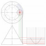
Visual Summary
Here is a drawn summary that may help you to visualize the development process:
Modifying the Template for use as a wrap-around cutting guide
x = pi(t + 2p)
x = needed template width
t = tank tube diameter
p = paper thickness (I find inkjet printer paper to be about .004″)
If you intend to use a paper wrap as a cutting guide, it needs to be made wider to fit around the tube. Take the actual tank tube diameter and add the thickness of two layers of paper to it. Multiply their sum by pi (3.14159). The resulting value is the needed X-dimension of the cutting guide wrap (sideways). Expand the template in the X direction only.
The resulting paper template may be slightly too large, so adjust the template width accordingly and reprint. The same thing can be done to make a cutting guide out of cardstock, fiberglass, or any other material, bearing in mind to only change the X-dimension of the template only.
Modifying the Template for rolling into a 2-layer cardstock tube
For the 1:59 scale Saturn model, I constructed the lowest portion of each tank tube from two layers of cardstock (the inside layer offset slightly upward to give the tank a nice sharp edge). The two layers would first be glued together flat, then curled and joined. The completed cardstock section would then be coupled to the main paper tube.
Due to the expansion/compression properties of two layers of cardstock that are glued before rolling, the template will need to be reduced in the X direction. I found that taking the average of the intended diameters of the tank [(O.D. + I.D.)/2] was an effective solution. The new circumference was then determined (pi x diameter), and the width of the template was modified accordingly and printed directly onto cardstock.
With some extra planning, a glue tab can be built into the design of the inner layer by offsetting the left and right edges of the bottom (inside) layer — see right.
